
In this tutorial we will see how to make a tracker to GPS tracker, with LORA and Arduino module. We will also see a basic webserver with ESP32, where you can open a URL on google maps, with real-time latitude and longitude data.
You may be interested in projects in Arduino, pic, robotics, telecommunications, subscribe http://www.youtube.com/user/carlosvolt?sub_confirmation=1 videos with full source code and diagrams

Electronic components
Two 1 Kohm resistors

Two LED diodes

Arduino nano

The Arduino Nano is a small board, complete and compatible with the test board based on the ATmega328 (Arduino Nano 3.x). It has about the same functionality as the Arduino Duemilanove, but in a different package. It only lacks a DC power connector and works with a Mini-B USB cable instead of a standard one.
| Microcontroller | ATmega328 |
| Architecture | Avr |
| Operating voltage | 5 V |
| Flash memory | 32 KB of which 2 KB uses the bootloader |
| Sram | 2 KB |
| Clock speed | 16 MHz |
| Analog pins IN | 8 |
| Eeprom | 1 KB |
| DC current by I/O pins | 40 mA (I/O pins) |
| Input voltage | 7-12 V |
| Digital I/O Pins | 22 (6 of which are PWM) |
| PWM output | 6 |
| Energy consumption | 19 mA |
| PCB size | 18 x 45 mm |
| Weight | 7g |
Pin diagram

Female pins

GT-7U GPS module

Note that when the GPS module works, the green indicator on the GPS module will flash (red is for power indication), and relative figures, time(UTC), latitude, longitude, and more. If we establish a connection between the GPS module, and a serial terminal program in our pc we will obtain data. It is important to try to be in a clear area to capture satellite signals, at least 3 satellites, to obtain latitude and longitude data, but the more satellites we get the better the navigation and accuracy experience.
Product description
Item Description: Features:
GT-U7 module. High sensitivity module, low static deviation, low power consumption and low volume.
Miniaturization: Thanks to the extremely high tracking sensitivity, the position of the cover has been considerably improved.
– High precision: In a narrow urban sky, in dense jungle environments, the GT-U7 can be positioned with great precision.
Easy to use: with IPEX antenna interface you can place the standard distribution of the active antenna quickly. Rechargeable button battery table. Onboard E2PROM enables the storage of parameter data.
-Compatible with: The output format is compatible with NEO-6M.
– Scope of application: vehicles, mobile devices such as PDA, vehicle surveillance, mobile phones, camcorders and other mobile location systems, bicycle sharing, common mobile power supply.
Package contents:
1 GT-U7 GPS module.
1 active antenna with IPEX interface.
Specification:
With IPEX antenna interface, the default distribution of the
active antenna, you can quickly place Operating voltage: 3.6V-5V (or direct USB power supply)
Baud transmission rate: 9600 (can be modified)
Rechargeable button battery on board
Onboard E2PROM
Memory NeMA output format of parameter data supports
NEO-6M Size: 27.6mm*26.6mm can be inserted or selected a patch (with positioning holes)
Application areas: Portable vehicle-mounted devices such
as PDA
Vehicle Monitoring Mobile phones, camcorders and other mobile positioning systems
Pinout
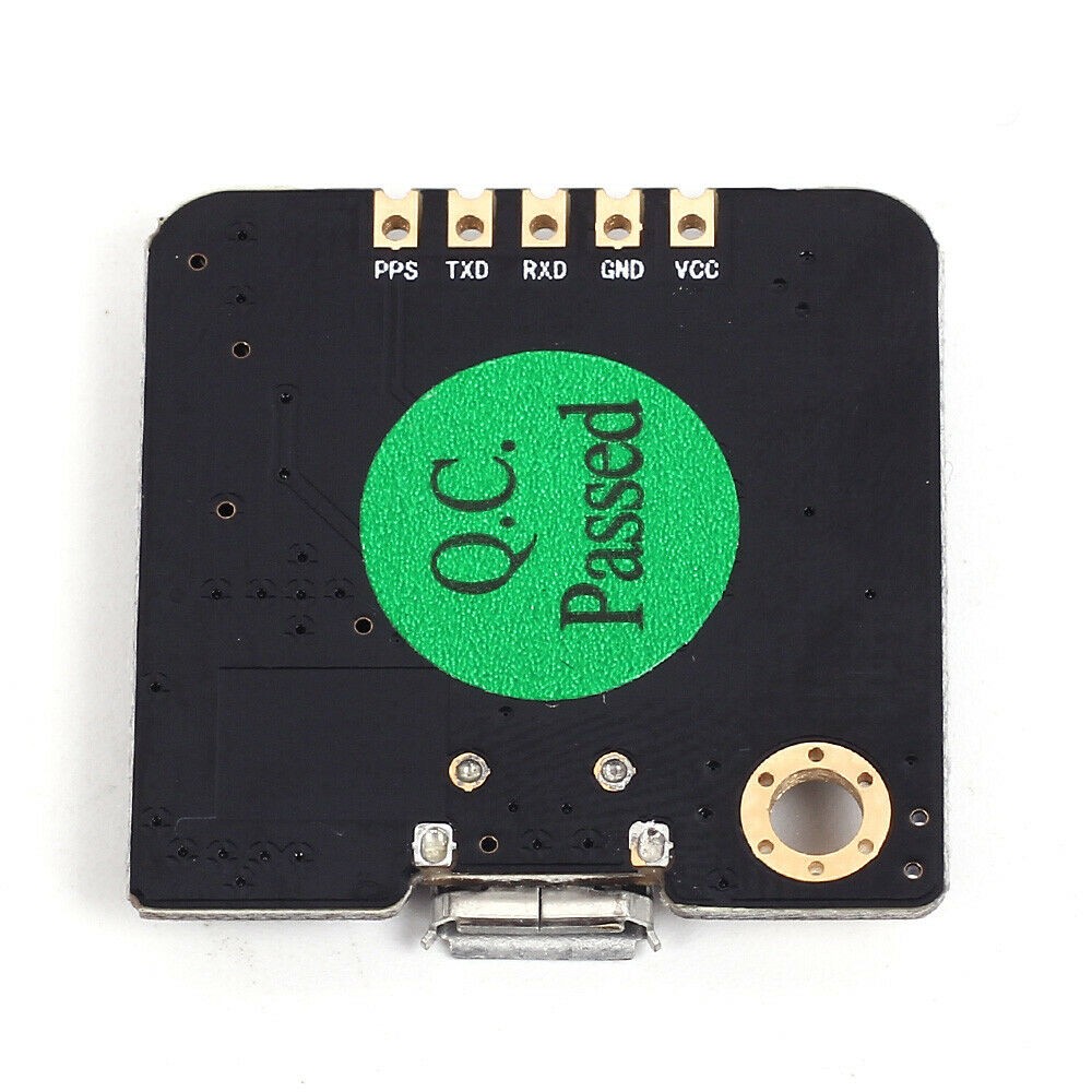
PPS: Pulse per second
TXD: Data transmission pin
RXD: Data transmission pin
GND: Earth
VCC: Power voltage 3.6 to 5.5 volts
Overview The
GT-U7 series of modules is a family of high performance autonomous GPS receivers with u-blox 6 positioning motor. These flexible and cost-effective receivers offer numerous connectivity options in a 16 x 12.2 x 2.4 mm miniature package. Its compact architecture and power and memory options make GT-U7 modules ideal for mobile
devices that run on battery-powered batteries with very strict cost and space constraints. The u-blox 6 50-channel positioning
engine features Time-To-First-Fix (TTFF) of less than 1 second. The dedicated acquisition engine, with 2 million correlators, is capable of performing massive time/frequency space searches in parallel, allowing you to
find satellites instantly. Innovative design and technology suppress interference sources and mitigate multipath effects, giving GT-U7 GPS receivers excellent navigation
performance even in most challenging environments.
Assisted GPS (A-GPS)
Providing help information such as ephemeris, almanaque,
last approximate position and hour and satellite status and an optional time sync signal will significantly reduce the time to fix for the first time and improve acquisition sensitivity. All GT-U7 modules are compatible with u-blox AssistNow Online and AssistNow Offline A-GPS11 services and are compatible with OMA SUPL.
AssistNow Autonomous
AssistNow Autonomous provides functionality similar to assisted GPS without the need for an external network host or connection. Based on satellite ephemeris data previously downloaded and stored by the GPS receiver, AssistNow Autonomous automatically generates accurate satellite orbital data (“AssistNow autonomous data”) that can be used for future GPS positions. AssistNow Autonomous data is reliable up to 3 days after initial capture.
Protocols and interfaces
Protocol type
INPUT/Output NMEA, ASCII, 0183, 2.3 (compatible with 3.0) UBX input/output, binary, u-blox patented RTCM input, 2.3
UART
GT-U7 modules include a configurable UART interface for serial communication.
USB
GT-U7 modules provide a USB version 2.0 FS interface (full speed, 12 Mbit/s) as an alternative to the UART. Pull-up resistance in USB_DP integrated to signal a full-speed device to the host. The VDDUSB pin supplies the USB interface. u-blox provides a Microsoft-certified USB driver® for Windows XP, Windows Vista, and Windows 7 operating systems.
Serial Peripheral Interface (SPI) The
SPI interface allows the connection of external devices with a serial interface, p. E.g. flash serial to save AssistNow Offline A-GPS settings and data or to connect to a host CPU. The interface can be operated in master or slave mode. In master mode, a chip selection signal is available for selecting external slaves. In slave mode, a single chip selection signal allows communication with the host.
Power management
U-blox receivers support different power modes. These modes represent strategies of how to control acquisition and tracking engines in order to achieve the best possible performance or good performance with reduced power consumption.
Maximum performance mode During
a cold start, a receiver in maximum performance mode continuously deploys the acquisition engine to search for all satellites. Once the receiver has a fixed position (or if pre-positioning information is available), the acquisition engine is still used to search for all visible satellites that are not being tracked.
Eco-mode
During a cold start, a receiver in Eco mode works exactly as in maximum performance mode. Once a position can be calculated and a sufficient number of satellites are being tracked, the acquisition engine shuts down, resulting in significant energy savings. The tracking engine continuously tracks purchased satellites and acquires other available or emerging satellites.
Power-saving mode
Power saving mode (PSM) allows a reduction in system power consumption by turning receiver parts on and off.
Lora Module

About Lora Modules
The LoRa radio module is a type of low-speed long-range data radio modem based on Semtech’s Sx1276. It is a low cost transceiver module of less than 1 GHz designed for operations in the ISM (Industrial Scientific Medical) and LPRD bands without license. Frequency spectrum modulation/demodulation, multichannel operation, high bandwidth efficiency and anti-lock performance make LoRa modules easy to perform thanks to robust and reliable wireless linking.
The module can operate in two different modes: standard mode and Star network mode. In standard mode, it acts as a transparent data radio modem that communicates with the host in the preset data format without the need for encoding/decoding. In startup network mode, a module will be configured for the central node and other modules will be configured as node modules. Communication between the central module and the node module is bidirectional, but node modules cannot communicate with each other. Note that the module does not contain the lorawan protocol. Therefore, the star network function of this module is used with the protocol itself, so it is not compatible with lorawan.
Features
- LoRa Frequency Spectrum
- Frequency band 433 / 490Mhz ISM
- -137 dBm receive sensitivity
- 20 dBm max. output power
- Serial activation port
- Wireless alarm clock
- Star network capacity
- Supply voltage 3.4 x 5.5V
Specification
- Operating Voltage: 2.1 x 3.6V (Battery Powered) or 4.5×5.5V
- Working frequency band: 433 MHz
- Modulation: LoRa extended spectrum
- Output power: ≤ 20dBm
- Reception sensitivity: -148dBm
- Emission current: ≤120mA
- Receiving current: ≤15.2mA
- Sleep current: ≤ 3.9uA
- Sleep time: optional 2S, 4S, 6S, 8S, 10S
- Breathing time: optional 2ms, 4ms, 8ms, 16ms, 32ms, 64ms
- Time to wake up: wake up immediately
- Communication interface: TTL serial communication
- Serial transmission speed: 1200 x 57600,9600bps (default)
- Serial port verification: 8E1.8O1.8N1 (optional)
- Operating temperature: -40oC – + 80oC
- Product size: 34.2 * 18.4mm / 1.35 * 0.72 inch


Data Sheets
PIN OUT

Connection Module with Serial USB adapter

SETTINGS
For some applications, default parameters may not be the best
option, so users may need to change the parameters There are two ways to adjust them: by MCU or by PC. In
configuration mode, the EN pin must be connected to
GND and then the configuration tool or commands can work effectively
By PC: DORJI offers a PC-based configuration tool
that can be used to change parameters through the graphical interface. Users can insert the DRF1278DM module into
serial usb adapter, and connect them to the computer and run the configuration tool.
DRF TOOL
This tool allows us to configure the LoRa MODULES DRF1278DM and DRF1276DM
Download—>DRFTOOL

Program description
UART -> Values are set to 9.6k bps and no parity check
RF frequency–> Indicates the central frequency of the RF carrier
RF Mode–> Standard Mode, Center Mode and Node Mode
RF_Factor–> Lora Scatter Factor. A higher value means
higher sensitivity but longer air transmission time. Only users can change it in standard mode
RF_BW–> Lora bandwidth. Higher value means less sensitivity. Recommended value: 125K. Only users can change it in standard mode.
Node ID–> Used only for node-mode modules: 0x65535
Net ID–> Only modules with the same network ID (0 x
255) can communicate with each other. You can avoid module interference
Power–> Used to configure the output power of the DRF1278D. There are 7 power levels. The 7 means the maximum. output power: 20dBm and 0 means the lowest output power
Breath–> The activation period for the module in node mode. Only available for firmware 2.0 or higher
Wake timer–> Time to detect wireless signal during break period, is only available for
firmware 2.7 or higher
Serial transmission rate–> Sets the data rate between DRF1278DM and the host (pc or microcontroller)
Serial Parity–> Defines the parity check between DRF1278DM and the host (pc or microcontroller)
STANDARD MODE Standard
mode is also called transparent mode in
which the module receives or sends data to the host over the serial port (UART) in the preset data format and users do not need to worry about the data processing within the module. The DRF1278DM AUX
pin will give indication about the IN/OUT data of the serial port 2 ms in advance, which can be used to wake up the host. In this mode, the EN pin must be set to
low logic in case the module enters deep sleep.
In STANDARD or transparent mode, nodes can work with a point-to-point (P2P) connection the main feature in this way is that no intermediary device is required to manage communication, devices can send information directly between them, this is perfect for simple communications such as turning on a light.
The other way is with a star network type where we find a central node that manages the network, its disadvantage is that it is limited to 255 255-node networks* and that the coordinator node can only listen to one node at a time.
STAR NETWORK MODE In
this mode, a DRF1278DM module needs to establish a module as a central module
and other modules must be node modules for star networks. For the central module, it works
at full performance so its power consumption is
the same as in standard mode and the EN pin must be connected to the low logic. The logical level of the
SET pin for the central module must be the same as the node module.
You may be interested in projects in Arduino, pic, robotics, telecommunications, subscribe http://www.youtube.com/user/carlosvolt?sub_confirmation=1 videos with full source code and diagrams
Printed circuit

Download the gerber file in –> Gerber_GPS_TRACKER_LORA_ARDUINO
Male pins

30-pin socket for Arduino

GPS Tracker Source Code
|
1 2 3 4 5 6 7 8 9 10 11 12 13 14 15 16 17 18 19 20 21 22 23 24 25 26 27 28 29 30 31 32 33 34 35 36 37 38 39 40 |
#include <SoftwareSerial.h>//Librería para emular un puerto serial por software #include <TinyGPS.h>//Librería para obtener datos del GPS TinyGPS gps; SoftwareSerial ss(4, 3);//Pines donde conectaremos el módulo GPS void setup() { Serial.begin(9600);//Velocidad del puerto serial del Arduino ss.begin(9600);//Velocidad del módulo GPS Serial.println("Iniciando envío de coordenadas con TinyGPS v. "); Serial.println(TinyGPS::library_version()); } void loop() { bool nuevosDatos = false; unsigned long caracteres; unsigned short sentencias, fallas; // Analizamos si hay datos del módulo GPS cada 5 segundos for (unsigned long start = millis(); millis() - start < 5000;) { while (ss.available())//Se cumple mientras hay datos disponibles desde el GPS { char c = ss.read(); if (gps.encode(c)) // Si hay datos validos nuevosDatos = true;//Asignamos un valor "true" a la variable } } if (nuevosDatos) { float flat, flon;//Variables para almacenar la latitud y longitud gps.f_get_position(&flat, &flon); Serial.print("https://maps.google.com/maps?q=");//Formato url de google maps Serial.print(flat == TinyGPS::GPS_INVALID_F_ANGLE ? 0.0 : flat, 6);//Obtenemos la latitud Serial.print(","); Serial.println(flon == TinyGPS::GPS_INVALID_F_ANGLE ? 0.0 : flon, 6);//Obtenemos la longitud } //En el caso de que exista una mala conexión con el GPS, en el cableado, nos enviará una alerta gps.stats(&caracteres, &sentencias, &fallas); if (caracteres == 0) Serial.println("*No se han recibido caracteres del GPS: compruebe el cableado*"); } |
Cicuito web server

Webserver Source Code
|
1 2 3 4 5 6 7 8 9 10 11 12 13 14 15 16 17 18 19 20 21 22 23 24 25 26 27 28 29 30 31 32 33 34 35 36 37 38 39 40 41 42 43 44 45 46 47 48 49 50 51 52 53 54 55 56 57 58 59 60 61 62 63 64 65 66 67 68 69 70 71 72 73 74 75 |
// Canal de youtube http://www.youtube.com/user/carlosvolt?sub_confirmation=1 //Tik-Tok https://www.tiktok.com/@carlosvolt //https://www.instagram.com/carlosvolt_electronic_robotic #include <WiFi.h> #include <Wire.h> String cadena; //Pines 16 y 17 para el módulo LORA #define RXD2 16 #define TXD2 17 //Atos de nuestra red wifi const char* ssid = "Tu_red_wifi"; const char* password = "Tu_clave_wifi"; WiFiServer server(80);//Puerto 80 para el navegador wep void setup() { Serial.begin(9600);//Velocidad del puerto Serial 1 Serial2.begin(9600,SERIAL_8N1,RXD2,TXD2);//Configuración del puerto serial 2 //Intentamos conectarnos a la red wifi Serial.print("Conectando a la red WiFi"); Serial.println(ssid); WiFi.begin(ssid, password); while (WiFi.status() != WL_CONNECTED) { delay(500); Serial.print("."); } Serial.println(""); //Si todo salió bien nos asigna una dirección ip que debemos colocar en el navegador Serial.println("Conectado con éxito a la red WiFi."); Serial.println("La dirección IP es: "); Serial.println(WiFi.localIP()); server.begin(); Serial.println("Servidor iniciado"); delay(2000); } void loop() { // Lectura de los caracteres en el terminal serial(si estan disponibles desde el módulo LORA) if (Serial2.available()) { cadena = String(""); while (Serial2.available()) { cadena = cadena + char(Serial2.read()); delay(1); } } //////Se cumple esta condición cada 5 segundos WiFiClient client = server.available(); if (client)//Si se cumple la condición, mostramos dotos en el webserver { Serial.println("Cliente web conectado "); String request = client.readStringUntil('\r'); client.println("HTTP/1.1 200 OK"); client.println("Content-type:text/html"); client.println("Connection: close"); client.println("Refresh: 5");//Refresco de la página web cada 5 segundos client.println(); client.println("<!DOCTYPE html><html>"); client.println("<head><meta name=\"viewport\" content=\"width=device-width, initial-scale=1\">"); client.println("<link rel=\"icon\" href=\"data:,\">"); client.println("</style></head><body><h1>Servidor Web con esp32 Gps Tracker arduino y Modulo LORA</h1>"); client.println("<h2>Tipo de GPS: GT-U7</h2>"); client.println("<h2>www.rogerbit.com</h2>"); client.println("<table><tr><th>Datos Obtenidos</th><th>Ubicacion</th></tr>"); client.println("<tr><td>Latitud y longitud:</td><td><span class=\"sensor\">"); client.println("<a href="); client.println(cadena);//Datos de lalitud y longitud client.println(">"); client.println(cadena);//Datos de lalitud y longitud para que los muestre como un hiper vinculo client.println("</a>"); client.println("</span></td></tr>"); client.println("</body></html>"); client.stop(); client.println(); Serial.println("Client disconnected."); Serial.println(""); } } |
Full project image with GPS tracker and webserver.

RECOMMENDED PROJECT