In this tutorial we will see how to make a rhythmic audio meter with the lm3915 integrated circuit. We will look at the list of electronic materials and components, also the assembly of the board step by step and talk about some features of the lm3915 integrated circuit.
Field of application
This integrated is used in the measurement of audio power levels, because the human ear has a logarithmic response to the level. In this way, the ignition of each LED will have a direct relationship with the sensation of the sound level. This built-in is application for audio uses as a rhythmic audio meter.
Tal vez pueda interesarte proyectos en arduino, pic, robótica, telecomunicaciones, suscribete en http://www.youtube.com/user/carlosvolt?sub_confirmation=1 mucho videos con código fuentes completos y diagramas

LM3915: Dot/Bar Display Controller
Overview
The LM3915 is a monolithic integrated circuit that detects analog voltage levels and activates ten LEDs, LCDs or vacuum fluorescent displays, which provide a 3 dB/step logarithmic analog sample. A pin changes the screen of a bar chart to a moving point screen. The LED current unit is programmable and adjustable, eliminating the need for current limiting resistors. The entire display system can operate from a single supply as low as 3V or as high as 25V.
The IC contains an adjustable voltage reference and a precise ten-step voltage divider. The high impedance input in the buffer accepts ground signals and up to 1.5 V of the positive offer. In addition, it does not need protection against ± 35V inputs. The input buffer drives 10 individual comparators referenced to the precision divider. Accuracy is usually better than 1 dB.
The LM3915’s 3 dB/step display is suitable for signals with wide dynamic range, such as audio level, power, light intensity or vibration. Audio applications include average or peak level indicators, power meters and RF signal power meters. Replacement of conventional meters with an LED bar.
The graph results in a faster, stronger response display with high visibility that preserves the ease of interpretation of an analog display.
The LM3915 is extremely easy to apply. A full 1.2V
scale The meter requires only one resistor in addition to the ten LEDs.
A more program resistance
the full scale from 1.2V to 12V regardless of the supply voltage. LED brightness is easily controlled with a single pot.
Features
- Handles up to 10 individual LEDs or displays to LEDs, LCDs, fluorescents or low-current incandescent lamps
- Expandable to displays up to 100 steps
- Bar mode display (all LEDs back on) or dot mode (single LED on)
- 10-step floating-point intercom divider that can be referenced over a wide range of voltages
- Internal voltage reference from 1.2 V to 12 V
- Regulated current and open collector outputs
- Outputs can be connected to TTL or CMOS
- Programmable output current from 2 mA to 30 mA, eliminating the need for resistors
- The inputs support up ±35 V without damage or falsely activating an output
- Dissipation max. encapsulation: 1365 mW
- Supply voltage: 3 V to 25 V
- Encapsulated: DIP 18-pin
The internal 10-step divider is floating and can
refer to a wide range of voltages The LM3915 is rated to operate from 0oC to +70oC. The LM3915N-1 is available in an 18-lead molded DIP package.
FUNCTIONAL DESCRIPTION
The LM3915’s simplified block diagram is included to give an overview of circuit operation. A large
input The impedance buffer operates with ground signals at 12V
and is protected against reverse and overvoltage signals. The signal is then applied to a series of 10 comparators; each of which is mewed
to a different level of comparison by the resistance chain.
In the illustrated example, the resistor chain is connected to the internal reference voltage of 1.25 V. In this case, for
every 3 dB that increases the input signal, one comparator will turn on another LED indicator. This
resistor The divider can be connected between any 2 voltages, provided they
are at least 1.5 V below V+ and not less than V-.
Voltage required at the input to turn on each LED
| Led | LM3914 | LM3915 |
|---|---|---|
| 1 | 125mV | 60mV |
| 2 | 250mV | 80mV |
| 3 | 375mV | 110mV |
| 4 | 500mV | 160mV |
| 5 | 625mV | 220mV |
| 6 | 750mV | 320mV |
| 7 | 875mV | 440mV |
| 8 | 1v | 630mV |
| 9 | 1,125V | 890mV |
| 10 | 1.25V | 1.25V |
Pinout

Block diagram

Cascading connection.
We can connect both cascading integrated circuits (two LM3915). This connection refers to adding the integrated circuits, to scale up twice or even more.

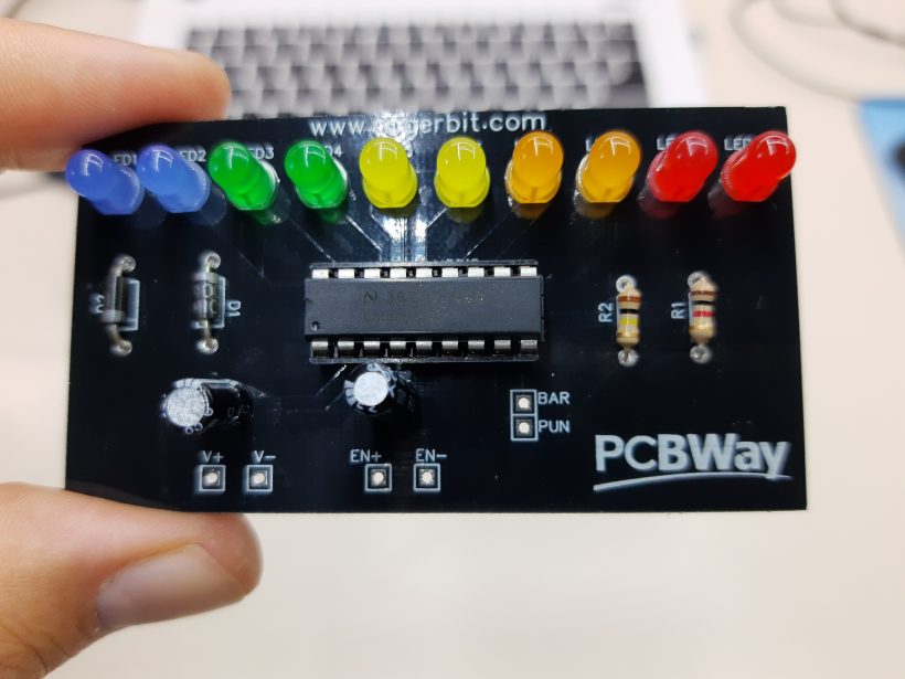
Circuit

Electronic diagram

Materials
A 1K resistor

Two diode 1N007

A 1uF capacitor

Un resistor de 100K

A jumper

Ten LED diode of different colors

An LM3915 integrated circuit

A printed circuit

Download Gerber File –> VÚMETRO_CON_LM3915
Male pins

18-pin socket


⭐️ SUBSCRIBE: https://www.youtube.com/user/carlosvolt?sub_confirmation=1 (Don’t forget to activate the 🔔)
👉Secondary channel: https://www.youtube.com/channel/UCjES9aB4g1F3IQbAk2nWCZg
👉Instagram: https://www.instagram.com/carlosvolt_tutoriales/
👉Tik Tok: https://www.tiktok.com/@carlosvolt
👉Fanpage: https://www.facebook.com/rogerbitfanpage/
👉Facebook: https://www.facebook.com/groups/RogerBit
👉Twitter: https://twitter.com/rogerbit_
👉Donations by paypal https://goo.gl/824Dnm or donacion@rogerbit.com
👉Website: https://www.rogerbit.com
SUBSCRIBE TO OUR NEWSLETTERS, RECEIVE IN YOUR EMAIL THE MOST OUTSTANDING NEWS, JUST BY ENTERING YOUR EMAIL
[wysija_form id=”1″]
RECOMMENDED VIDEO