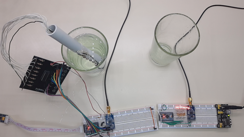
In this tutorial we will see how to create a system that allows us to measure the water level remotely, with modules lora DRF1278DM/DRF1276DM (sx1276) and arduino mini pro, in addition the printed circuit is included to create the water probe. We will see the circuits, also the source codes and the operation of the system.
About the Water Level Meter Circuit
The ULN2803 integrated circuit is used as a power interface for circuits with CMOS and TTL technology. This integrated has inside 8 NPN transistors in Darlington configuration with protective diodes, to be able to control motors, inductive loads, relays, and more. Each output can control up to 500 mA so you can control different types of loads. Outputs can be connected in parallel when higher loads need to be handled, however it is advisable not to exceed the total power of the circuit.
You may be interested in projects in Arduino, pic, robotics, telecommunications, http://www.youtube.com/user/carlosvolt?sub_confirmation=1 videos with full source code and diagrams

Features:
-
- 8 NPN Darlington transistors in common emitter
- 8 reverse voltage suppression diodes to handle inductive loads, with common cathode connections
- Outputs of 0.5A (500mA) max.
- Transistors can be connected in parallel for greater current capacity
- Output support voltage: -0.5V to 50V
- Max power: 1.47 W
- Input resistance to the base: 2.7k
- Input voltage: -0.5V to 30V
- 5V TTL and CMOS compatible inputs
- Encapsulated: DIP 18-pin
Applications:
- Command of relays, lamps, or displays (LED or gas discharge), etc.
- Logical buffers
- Line drivers
- Among other applications
Operation
To activate each output of this integrated circuit, the water must not be pure, in its contents it must have some salts, which help to conduct electricity, that when reaching each of the levels in the container, closes the electrical circuit of the ulN2803 inputs, which detect the high voltage level and turns on the LED corresponding to each output. At each output we can connect for example a relay, a buzzer and even the pump of an engine to refill a water tank, if necessary, up to a certain level and disconnect the water pump when reaching the desired limit.
The following figure shows the ULN2803 pinout. Comes with 8 input pins and 8 output pins.

The following figure shows the logical diagram of ULN2803. It is a visual representation and arrangement of how diodes are connected in the component.

The following figure shows the schematic diagram for each pair of Darlington.

Materiales
8 resistores de un 1K

8 10K resistors

Male pins

An integrated circuit uln2803apg

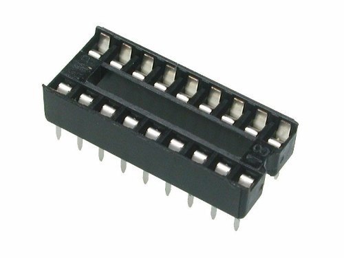
An 18-pin socket
A printed circuit

Download gerber file Gerber_circuito water level meter
Diagram

About Lora Modules
The LoRa radio module is a type of low-speed long-range data radio modem based on Semtech’s Sx1276. It is a low cost transceiver module of less than 1 GHz designed for operations in the ISM (Industrial Scientific Medical) and LPRD bands without license. Frequency spectrum modulation/demodulation, multichannel operation, high bandwidth efficiency and anti-lock performance make LoRa modules easy to perform thanks to robust and reliable wireless linking.
The module can operate in two different modes: standard mode and Star network mode. In standard mode, it acts as a transparent data radio modem that communicates with the host in the preset data format without the need for encoding/decoding. In startup network mode, a module will be configured for the central node and other modules will be configured as node modules. Communication between the central module and the node module is bidirectional, but node modules cannot communicate with each other. Note that the module does not contain the lorawan protocol. Therefore, the star network function of this module is used with the protocol itself, so it is not compatible with lorawan.
Features
- LoRa Frequency Spectrum
- Frequency band 433 / 490Mhz ISM
- -137 dBm receive sensitivity
- 20 dBm max. output power
- Serial activation port
- Wireless alarm clock
- Star network capacity
- Supply voltage 3.4 x 5.5V
Specification
- Operating Voltage: 2.1 x 3.6V (Battery Powered) or 4.5×5.5V
- Working frequency band: 433 MHz
- Modulation: LoRa extended spectrum
- Output power: ≤ 20dBm
- Reception sensitivity: -148dBm
- Emission current: ≤120mA
- Receiving current: ≤15.2mA
- Sleep current: ≤ 3.9uA
- Sleep time: optional 2S, 4S, 6S, 8S, 10S
- Breathing time: optional 2ms, 4ms, 8ms, 16ms, 32ms, 64ms
- Time to wake up: wake up immediately
- Communication interface: TTL serial communication
- Serial transmission speed: 1200 x 57600,9600bps (default)
- Serial port verification: 8E1.8O1.8N1 (optional)
- Operating temperature: -40oC – + 80oC
- Product size: 34.2 * 18.4mm / 1.35 * 0.72 inch


Data Sheets
PIN OUT

Connection Module with Serial USB adapter

SETTINGS
For some applications, default parameters may not be the best
option, so users may need to change the parameters There are two ways to adjust them: by MCU or by PC. In
configuration mode, the EN pin must be connected to
GND and then the configuration tool or commands can work effectively
By PC: DORJI offers a PC-based configuration tool
that can be used to change parameters through the graphical interface. Users can insert the DRF1278DM module into
serial usb adapter, and connect them to the computer and run the configuration tool.
DRF TOOL
This tool allows us to configure the LoRa MODULES DRF1278DM and DRF1276DM
Download—>DRFTOOL

Program description
UART -> Values are set to 9.6k bps and no parity check
RF frequency–> Indicates the central frequency of the RF carrier
RF Mode–> Standard Mode, Center Mode and Node Mode
RF_Factor–> Lora Scatter Factor. A higher value means
higher sensitivity but longer air transmission time. Only users can change it in standard mode
RF_BW–> Lora bandwidth. Higher value means less sensitivity. Recommended value: 125K. Only users can change it in standard mode.
Node ID–> Used only for node-mode modules: 0x65535
Net ID–> Only modules with the same network ID (0 x
255) can communicate with each other. You can avoid module interference
Power–> Used to configure the output power of the DRF1278D. There are 7 power levels. The 7 means the maximum. output power: 20dBm and 0 means the lowest output power
Breath–> The activation period for the module in node mode. Only available for firmware 2.0 or higher
Wake timer–> Time to detect wireless signal during break period, is only available for
firmware 2.7 or higher
Serial transmission rate–> Sets the data rate between DRF1278DM and the host (pc or microcontroller)
Serial Parity–> Defines the parity check between DRF1278DM and the host (pc or microcontroller)
STANDARD MODE Standard
mode is also called transparent mode in
which the module receives or sends data to the host over the serial port (UART) in the preset data format and users do not need to worry about the data processing within the module. The DRF1278DM AUX
pin will give indication about the IN/OUT data of the serial port 2 ms in advance, which can be used to wake up the host. In this mode, the EN pin must be set to
low logic in case the module enters deep sleep.
In STANDARD or transparent mode, nodes can work with a point-to-point (P2P) connection the main feature in this way is that no intermediary device is required to manage communication, devices can send information directly between them, this is perfect for simple communications such as turning on a light.
The other way is with a star network type where we find a central node that manages the network, its disadvantage is that it is limited to 255 255-node networks* and that the coordinator node can only listen to one node at a time.
STAR NETWORK MODE In
this mode, a DRF1278DM module needs to establish a module as a central module
and other modules must be node modules for star networks. For the central module, it works
at full performance so its power consumption is
the same as in standard mode and the EN pin must be connected to the low logic. The logical level of the
SET pin for the central module must be the same as the node module.
Transmitter circuit

Transmitter source code
|
1 2 3 4 5 6 7 8 9 10 11 12 13 14 15 16 17 18 19 20 21 22 23 24 25 26 27 28 29 30 31 32 33 34 35 36 37 38 39 40 41 42 43 44 45 46 47 48 49 50 51 52 53 54 55 56 57 58 59 60 61 62 63 64 65 66 67 68 69 70 71 72 73 74 75 76 77 78 79 80 81 82 83 84 85 |
//Transmisor de nivel de agua con módulo lora //Más proyectos en http://www.rogerbit.com //Suscribete en http://www.youtube.com/user/carlosvolt?sub_confirmation=1 //Grupo en Facebook https://www.facebook.com/groups/RogerBit/ //declaración de variables int pin2 = 2; int pin3 = 3; int pin4 = 4; int pin5 = 5; int pin6 = 6; int pin7 = 7; int pin8 = 8; int pin9 = 9; //// int lpin2 = 0; int lpin3 = 0; int lpin4 = 0; int lpin5 = 0; int lpin6 = 0; int lpin7 = 0; int lpin8 = 0; int lpin9 = 0; int transistor = 10; void setup() { Serial.begin(9600);//Velocidad dle puerto serie debe ser la misma del módulo lora //Configuramos estos pines como entrada para la sonda de agua pinMode(pin2, INPUT_PULLUP); pinMode(pin3, INPUT_PULLUP); pinMode(pin4, INPUT_PULLUP); pinMode(pin5, INPUT_PULLUP); pinMode(pin6, INPUT_PULLUP); pinMode(pin7, INPUT_PULLUP); pinMode(pin8, INPUT_PULLUP); pinMode(pin9, INPUT_PULLUP); //Pin 10 como salida pinMode(transistor, OUTPUT); } void loop() { //Activamos el transistor durante un tiempo corto para evitar la electrolisis del agua y ahorrar energía digitalWrite(transistor, HIGH); delay(100); //Lectura de la sonda tiene en total 8 niveles lpin2 = digitalRead(pin2); lpin3 = digitalRead(pin3); lpin4 = digitalRead(pin4); lpin5 = digitalRead(pin5); lpin6 = digitalRead(pin6); lpin7 = digitalRead(pin7); lpin8 = digitalRead(pin8); lpin9 = digitalRead(pin9); delay(100); //Desactivamos el transistor y con ello el uln2803 digitalWrite(transistor, LOW); //Comparamos el valor de cada pin y en base ha eso enviaremos un dato al puerto serie if(lpin2 == LOW && lpin3 == LOW && lpin4 == LOW && lpin5 == LOW && lpin6 == LOW && lpin7 == LOW && lpin8 == LOW && lpin9 == LOW){ Serial.print("9"); } if(lpin2 == HIGH && lpin3 == LOW && lpin4 == LOW && lpin5 == LOW && lpin6 == LOW && lpin7 == LOW && lpin8 == LOW && lpin9 == LOW){ Serial.print("8"); } if(lpin2 == HIGH && lpin3 == HIGH && lpin4 == LOW && lpin5 == LOW && lpin6 == LOW && lpin7 == LOW && lpin8 == LOW && lpin9 == LOW){ Serial.print("7"); } if(lpin2 == HIGH && lpin3 == HIGH && lpin4 == HIGH && lpin5 == LOW && lpin6 == LOW && lpin7 == LOW && lpin8 == LOW && lpin9 == LOW){ Serial.print("6"); } if(lpin2 == HIGH && lpin3 == HIGH && lpin4 == HIGH && lpin5 == HIGH && lpin6 == LOW && lpin7 == LOW && lpin8 == LOW && lpin9 == LOW){ Serial.print("5"); } if(lpin2 == HIGH && lpin3 == HIGH && lpin4 == HIGH && lpin5 == HIGH && lpin6 == HIGH && lpin7 == LOW && lpin8 == LOW && lpin9 == LOW){ Serial.print("4"); } if(lpin2 == HIGH && lpin3 == HIGH && lpin4 == HIGH && lpin5 == HIGH && lpin6 == HIGH && lpin7 == HIGH && lpin8 == LOW && lpin9 == LOW){ Serial.print("3"); } if(lpin2 == HIGH && lpin3 == HIGH && lpin4 == HIGH && lpin5 == HIGH && lpin6 == HIGH && lpin7 == HIGH && lpin8 == HIGH && lpin9 == LOW){ Serial.print("2"); } if(lpin2 == HIGH && lpin3 == HIGH && lpin4 == HIGH && lpin5 == HIGH && lpin6 == HIGH && lpin7 == HIGH && lpin8 == HIGH && lpin9 == HIGH){ Serial.print("1"); } delay(1000); } |
Receiver circuit

Receiver source code
|
1 2 3 4 5 6 7 8 9 10 11 12 13 14 15 16 17 18 19 20 21 22 23 24 25 26 27 28 29 30 31 32 33 34 35 36 37 38 39 40 41 42 43 44 45 46 47 48 49 50 51 52 53 54 55 56 57 58 59 60 61 62 63 64 65 66 67 68 69 70 71 72 73 74 75 76 77 78 79 80 81 82 83 84 85 86 87 88 89 90 91 92 93 94 95 96 97 98 99 100 101 102 103 104 105 106 107 108 109 110 111 112 113 114 115 116 117 118 119 120 121 122 123 124 125 126 127 128 129 130 131 132 133 134 135 136 137 138 139 140 141 142 143 144 145 146 |
//Receptor nivel de agua con módulo lora //Más proyectos en http://www.rogerbit.com //Suscribete en http://www.youtube.com/user/carlosvolt?sub_confirmation=1 //Grupo en Facebook https://www.facebook.com/groups/RogerBit/ //declaración de variables String cadena; int pin2 = 2; int pin3 = 3; int pin4 = 4; int pin5 = 5; int pin6 = 6; int pin7 = 7; int pin8 = 8; int pin9 = 9; void setup () { Serial.begin(9600);// setea la velocidad del puerto serial según la velocidad del módulo lora //Pines declaraods como salidas pinMode(pin2, OUTPUT); pinMode(pin3, OUTPUT); pinMode(pin4, OUTPUT); pinMode(pin5, OUTPUT); pinMode(pin6, OUTPUT); pinMode(pin7, OUTPUT); pinMode(pin8, OUTPUT); pinMode(pin9, OUTPUT); } void loop () { //lee las cadenas que ingresan al puerto serie if (Serial.available()) { cadena = String(""); while (Serial.available()) { cadena = cadena + char(Serial.read()); delay(1); } if (cadena == "9") {//compara el valor de la cadena obetinada //Enciende todos los led indicando el tanque de agua al 100 porciento digitalWrite(pin2,HIGH); digitalWrite(pin3,HIGH); digitalWrite(pin4,HIGH); digitalWrite(pin5,HIGH); digitalWrite(pin6,HIGH); digitalWrite(pin7,HIGH); digitalWrite(pin8,HIGH); digitalWrite(pin9,HIGH); } if (cadena == "8") {//compara el valor de la cadena obetinada //Enciende 7 led indicando el tanque de agua al 87 porciento digitalWrite(pin2,HIGH); digitalWrite(pin3,HIGH); digitalWrite(pin4,HIGH); digitalWrite(pin5,HIGH); digitalWrite(pin6,HIGH); digitalWrite(pin7,HIGH); digitalWrite(pin8,HIGH); digitalWrite(pin9,LOW); } if (cadena == "7") {//compara el valor de la cadena obetinada //Enciende 6 led indicando el tanque de agua al 75 porciento digitalWrite(pin2,HIGH); digitalWrite(pin3,HIGH); digitalWrite(pin4,HIGH); digitalWrite(pin5,HIGH); digitalWrite(pin6,HIGH); digitalWrite(pin7,HIGH); digitalWrite(pin8,LOW); digitalWrite(pin9,LOW); } if (cadena == "6") {//compara el valor de la cadena obetinada //Enciende 5 led indicando el tanque de agua al 63 porciento digitalWrite(pin2,HIGH); digitalWrite(pin3,HIGH); digitalWrite(pin4,HIGH); digitalWrite(pin5,HIGH); digitalWrite(pin6,HIGH); digitalWrite(pin7,LOW); digitalWrite(pin8,LOW); digitalWrite(pin9,LOW); } if (cadena == "5") {//compara el valor de la cadena obetinada //Enciende 4 led indicando el tanque de agua al 50 porciento digitalWrite(pin2,HIGH); digitalWrite(pin3,HIGH); digitalWrite(pin4,HIGH); digitalWrite(pin5,HIGH); digitalWrite(pin6,LOW); digitalWrite(pin7,LOW); digitalWrite(pin8,LOW); digitalWrite(pin9,LOW); } //Activa la bocina if (cadena == "4") { //Enciende 3 led indicando el tanque de agua al 37 porciento digitalWrite(pin2,HIGH); digitalWrite(pin3,HIGH); digitalWrite(pin4,HIGH); digitalWrite(pin5,LOW); digitalWrite(pin6,LOW); digitalWrite(pin7,LOW); digitalWrite(pin8,LOW); digitalWrite(pin9,LOW); } //Desactiva la bocina if (cadena == "3") { // Enciende 2 led indicando el tanque de agua al 25 porciento digitalWrite(pin2,HIGH); digitalWrite(pin3,HIGH); digitalWrite(pin4,LOW); digitalWrite(pin5,LOW); digitalWrite(pin6,LOW); digitalWrite(pin7,LOW); digitalWrite(pin8,LOW); digitalWrite(pin9,LOW); } //Enciende la luz if (cadena == "2") { //Enciende 1 led indicando el tanque de agua al 12 porciento digitalWrite(pin2,HIGH); digitalWrite(pin3,LOW); digitalWrite(pin4,LOW); digitalWrite(pin5,LOW); digitalWrite(pin6,LOW); digitalWrite(pin7,LOW); digitalWrite(pin8,LOW); digitalWrite(pin9,LOW); } //Apaga la luz if (cadena == "1") { //Todos los led apagados, indicando el tanque de agua vacio digitalWrite(pin2,LOW); digitalWrite(pin3,LOW); digitalWrite(pin4,LOW); digitalWrite(pin5,LOW); digitalWrite(pin6,LOW); digitalWrite(pin7,LOW); digitalWrite(pin8,LOW); digitalWrite(pin9,LOW); } Serial.print(cadena); } } |
SUBSCRIBE TO OUR NEWSLETTERS, RECEIVE IN YOUR EMAIL THE MOST OUTSTANDING NEWS, JUST BY ENTERING YOUR EMAIL
[wysija_form id=”1″]
RECOMMENDED VIDEO