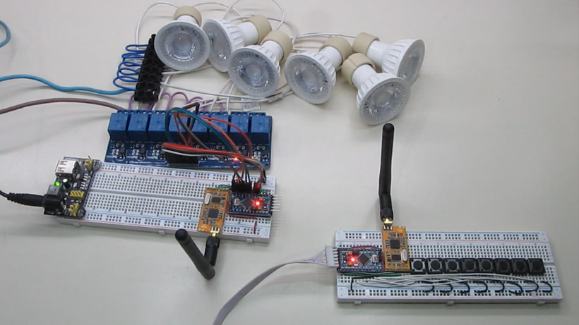
In this tutorial we will use the radio frequency modules apc220 and arduino mini pro, to turn on lights or any other device, at a distance of up to one kilometer. This project is ideal for controlling devices, where there is no possibility of having internet to control them.
Plates and modules used in this project
Arduino mini pro
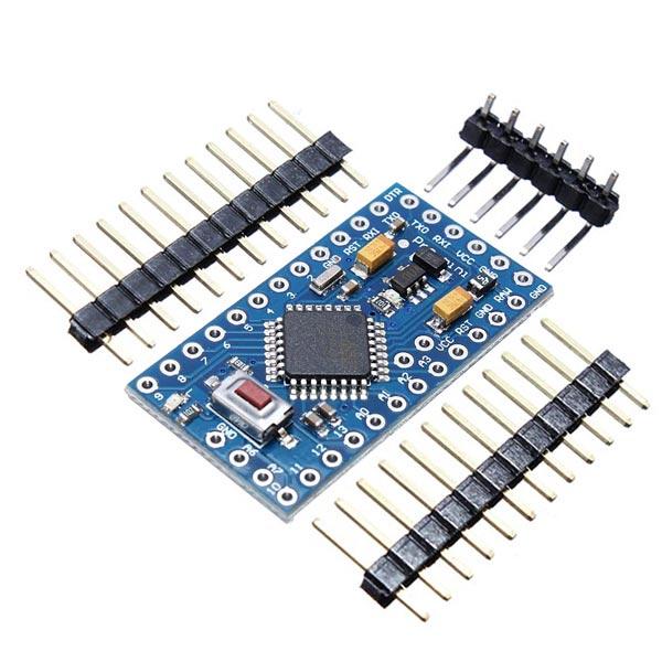
The Arduino Pro Mini is a microcontroller board based on the ATmega328.
It has 14 digital input/output pins (of which 6 can be used as PWM outputs), 6 analog inputs, an integrated resonator, a reset button and holes to mount pin headers. A six-pin header can be connected to an FTDI cable or Sparkfun connection board to provide USB power and communication to the board.
The Arduino Pro Mini is designed for semi-permanent installation in objects or exhibitions. The board comes without pre-assembled headers, allowing the use of various types of connectors or direct cable welding. The pin design is compatible with the Arduino Mini.
There are two versions of the Pro Mini. One runs at 3.3V and 8 MHz, the other at 5V and 16 MHz.
| Microcontroller | ATmega328 * |
| Board power supply | 3.35-12 V (3.3 V model) or 5-12 V (5 V model) |
| Circuit operating voltage | 3.3V or 5V (depending on model) |
| Digital I/O Pins | 14 |
| PWM pins | 6 6 |
| Uart | 1 |
| Spi | 1 |
| I2c | 1 |
| Analog input pins | 6 6 |
| External outages | 2 |
| DC current per I/O pin | 40 mA |
| Flash memory | 32 KB of which 2 KB used by the bootloader * |
| Sram | 2 KB * |
| Eeprom | 1 KB * |
| Clock speed | 8 MHz (3.3V versions) or 16 MHz (5V versions) |
Module Apc220
The APC220 radio data module is a highly versatile, high-power radio solution that is easy to set up and integrate into any project that requires a wireless RF link. It is perfect for robotic applications if you need wireless control. You can connect one of these modules to your MCU via the TTL interface, and connect to your PC with another APC220 module via a TTL/USB converter.
Specification
- Working frequency: 420 MHz to 450 MHz
- Power: 3.5-5.5V
- Current: <25-35mA
- Working temperature: -20oC + 70oC
- Range: 1200 m line of sight (1200 bps)
- Interface: UART/ TTL
- Transmission speed: 1200-19200 bps
- Transmission speed (air): 1200-19200 bps
- Receive buffer: 256 bytes
- Size: 37mm × 17mm × 6.6mm
- Weight: 30g
You may be interested in projects in Arduino, pic, robotics, telecommunications, subscribe http://www.youtube.com/user/carlosvolt?sub_confirmation=1 videos with full source code and diagrams

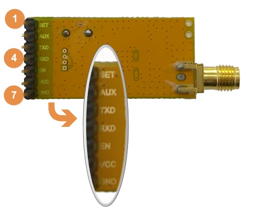
Pinout
| Pin | Definition | Detail |
|---|---|---|
| 1 | Set | Set parameters (low) |
| 2 | Aux | UART signal- Transmission (low) Transmission (high) |
| 3 | Txd | UART TX |
| 4 | Rxd | UART RX |
| 5 | Is | Turn off the device when you apply <0.5 V. Enable the device when you leave it offline or apply > 1.6 V |
| 6 | Vdc | 3.3V-5.5V power |
| 7 | Gnd | Earth 0V |
Download RF-Magic
Datasheet
Run APC22X_V12A.exe (RF-Magic) as an administrator if your system is not Windows XP.

NOTE: In the software you will recognize the APC220 module and COMX serial port automatically once we open it. Check in Device Manager to verify the correct COM port.
Configure RF-magic as in the red square frame below (default setting), and click Write W to enter your settings, then click Read R to read the parameters you have set.

Configuration

Writing and reading settings
| Parameter | Range | Default |
|---|---|---|
| RF frequency | 1KHz resolution, 100Hz ± accuracy | 434MHz |
| TRx RF Rate | 1200, 2400, 4800, 9600, 19200 bps | 9600bps |
| RF power | 0-9 | 9 |
| Serial rate | 1200, 2400, 4800, 9600, 19200, 38400, 57600bps | 9600bps |
| NET ID | 0-65535 (16-bit) | 12345 |
| NODE ID | 123456789012 | |
| Patity Series | Disable, the strange Patity, even Patity | Disable |
Configure the other APC220 module in the same way, with the same parameter settings.
8-channel Relay rele module

- Operating Voltage: 5V DC
- Control Signal: TTL (3.3V or 5V)
- Number of Relays (channels): 8 CH
- Max capacity: 10A/250VAC, 10A/30VDC
- Max current: 10A (NO), 5A (NC)
- Action time: 10 ms/5 ms
- To activate output NO: 0 Volts
Emitting control circuit
The emitting circuit consists of the acp220 module, an Arduino mini pro and 8 Tact Switch type pushbuttons.
The apc220 can power them with 3.3 to 5.5 volts, this version of arduino mini pro is 5 volts so we will power the whole circuit with that voltage.
The Arduino transmitter pin must be connected to the receiver pin of the apc220 module, and vice versa, so that they can communicate with each other.

Source code issuing control
|
1 2 3 4 5 6 7 8 9 10 11 12 13 14 15 16 17 18 19 20 21 22 23 24 25 26 27 28 29 30 31 32 33 34 35 36 37 38 39 40 41 42 43 44 45 46 47 48 49 50 51 52 53 54 55 56 57 58 59 60 61 62 63 64 65 66 67 68 69 70 71 72 73 74 75 76 77 78 79 80 81 82 83 84 85 86 87 88 89 90 91 92 93 94 95 96 97 98 99 100 101 102 103 104 105 106 107 108 109 110 111 112 113 114 115 116 117 118 119 120 121 122 123 124 125 126 127 128 129 130 131 132 133 134 135 136 137 138 139 140 141 142 143 144 145 146 147 148 149 150 151 152 153 154 155 156 157 158 159 160 161 162 163 |
//declaración de variables int pul2 = 0; int pul3 = 0; int pul4 = 0; int pul5 = 0; int pul6 = 0; int pul7 = 0; int pul8 = 0; int pul9 = 0; int estado2 = 0; int estado3 = 0; int estado4 = 0; int estado5 = 0; int estado6 = 0; int estado7 = 0; int estado8 = 0; int estado9 = 0; void setup() { Serial.begin(9600);//Velocidad del puerto serial pinMode(2, INPUT_PULLUP); pinMode(3, INPUT_PULLUP); pinMode(4, INPUT_PULLUP); pinMode(5, INPUT_PULLUP); pinMode(6, INPUT_PULLUP); pinMode(7, INPUT_PULLUP); pinMode(8, INPUT_PULLUP); pinMode(9, INPUT_PULLUP); } void loop() { //Lectura de botones pul2 = digitalRead(2); pul3 = digitalRead(3); pul4 = digitalRead(4); pul5 = digitalRead(5); pul6 = digitalRead(6); pul7 = digitalRead(7); pul8 = digitalRead(8); pul9 = digitalRead(9); //Enciende o apaga la luz if (pul2 == LOW) {//Si el pulsador 2 está precionado se cumple esta condición pul2 = digitalRead(2);//Leemos el estado del botón nuevamente if(estado2 ==0){//Si la variable estado2 es igual a 0 se cumple esta condición Serial.print("luz2on");// Enviamos esta cadena de caracteres x el puerto serial para encender la luz estado2 =1;//Asignamos el valor 1 a la variable "estado2" } else{ Serial.print("luz2off");//Enviamos esta cadena para apagar la luz estado2 =0; } while(pul2 == LOW){ pul2 = digitalRead(2);//Se cumple esta condición mientras esté precionado el botón } } //----------------------------------------------------------------------------------- //Enciende o apaga la luz if (pul3 == LOW) {//Si el pulsador 3 está precionado se cumple esta condición pul3 = digitalRead(3);//Leemos el estado del botón nuevamente if(estado3 ==0){//Si la variable estado3 es igual a 0 se cumple esta condición Serial.print("luz3on");// Enviamos esta cadena de caracteres x el puerto serial para encender la luz estado3 =1;//Asignamos el valor 1 a la variable "estado3" } else{ Serial.print("luz3off");//Enviamos esta cadena para apagar la luz estado3 =0; } while(pul3 == LOW){ pul3 = digitalRead(3);//Se cumple esta condición mientras esté precionado el botón } } //----------------------------------------------------------------------------------- //Enciende o apaga la luz if (pul4 == LOW) {//Si el pulsador 4 está precionado se cumple esta condición pul4 = digitalRead(4);//Leemos el estado del botón nuevamente if(estado4 ==0){//Si la variable estado4 es igual a 0 se cumple esta condición Serial.print("luz4on");// Enviamos esta cadena de caracteres x el puerto serial para encender la luz estado4 =1;//Asignamos el valor 1 a la variable "estado4" } else{ Serial.print("luz4off");//Enviamos esta cadena para apagar la luz estado4 =0; } while(pul4 == LOW){ pul4 = digitalRead(4);//Se cumple esta condición mientras esté precionado el botón } } //----------------------------------------------------------------------------------- //Enciende o apaga la luz if (pul5 == LOW) {//Si el pulsador 5 está precionado se cumple esta condición pul5 = digitalRead(5);//Leemos el estado del botón nuevamente if(estado5 ==0){//Si la variable estado5 es igual a 0 se cumple esta condición Serial.print("luz5on");// Enviamos esta cadena de caracteres x el puerto serial para encender la luz estado5 =1;//Asignamos el valor 1 a la variable "estado5" } else{ Serial.print("luz5off");//Enviamos esta cadena para apagar la luz estado5 =0; } while(pul5 == LOW){ pul5 = digitalRead(5);//Se cumple esta condición mientras esté precionado el botón } } //----------------------------------------------------------------------------------- //Enciende o apaga la luz if (pul6 == LOW) {//Si el pulsador 6 está precionado se cumple esta condición pul6 = digitalRead(6);//Leemos el estado del botón nuevamente if(estado6 ==0){//Si la variable estado6 es igual a 0 se cumple esta condición Serial.print("luz6on");// Enviamos esta cadena de caracteres x el puerto serial para encender la luz estado6 =1;//Asignamos el valor 1 a la variable "estado6" } else{ Serial.print("luz6off");//Enviamos esta cadena para apagar la luz estado6 =0; } while(pul6 == LOW){ pul6 = digitalRead(6);//Se cumple esta condición mientras esté precionado el botón } } //----------------------------------------------------------------------------------- //Enciende o apaga la luz if (pul7 == LOW) {//Si el pulsador 7 está precionado se cumple esta condición pul7 = digitalRead(7);//Leemos el estado del botón nuevamente if(estado7 ==0){//Si la variable estado7 es igual a 0 se cumple esta condición Serial.print("luz7on");// Enviamos esta cadena de caracteres x el puerto serial para encender la luz estado7 =1;//Asignamos el valor 1 a la variable "estado7" } else{ Serial.print("luz7off");//Enviamos esta cadena para apagar la luz estado7 =0; } while(pul7 == LOW){ pul7 = digitalRead(7);//Se cumple esta condición mientras esté precionado el botón } } //----------------------------------------------------------------------------------- //Enciende o apaga la luz if (pul8 == LOW) {//Si el pulsador 8 está precionado se cumple esta condición pul8 = digitalRead(8);//Leemos el estado del botón nuevamente if(estado8 ==0){//Si la variable estado8 es igual a 0 se cumple esta condición Serial.print("luz8on");// Enviamos esta cadena de caracteres x el puerto serial para encender la luz estado8 =1;//Asignamos el valor 1 a la variable "estado8" } else{ Serial.print("luz8off");//Enviamos esta cadena para apagar la luz estado8 =0; } while(pul8 == LOW){ pul8 = digitalRead(8);//Se cumple esta condición mientras esté precionado el botón } } //----------------------------------------------------------------------------------- //Enciende o apaga la luz if (pul9 == LOW) {//Si el pulsador 9 está precionado se cumple esta condición pul9 = digitalRead(9);//Leemos el estado del botón nuevamente if(estado9 ==0){//Si la variable estado9 es igual a 0 se cumple esta condición Serial.print("luz9on");// Enviamos esta cadena de caracteres x el puerto serial para encender la luz estado9 =1;//Asignamos el valor 1 a la variable "estado9" } else{ Serial.print("luz9off");//Enviamos esta cadena para apagar la luz estado9 =0; } while(pul9 == LOW){ pul9 = digitalRead(9);//Se cumple esta condición mientras esté precionado el botón } } //----------------------------------------------------------------------------------- delay(50); } |
Receiver circuit with relay module
The receiver circuit also has an apc220 module and an Arduino mini pro, replaces the 8 pushbuttons with an 8-channel relay module for the control of the lights or any other device, 110/220 volts.

CAUTION: THIS MODULE WORKS WITH VERY DANGEROUS AC VOLTAGES, WHICH CAN CAUSE ELECTROCUTION AND VERY POSSIBLE DEATH, IF THE NECESSARY SAFETY MEASURES ARE NOT TAKEN. IF YOU HAVE NEVER WORKED WITH SUCH MODULES SEEK ADVICE FROM A QUALIFIED PROFESSIONAL, WE ARE NOT RESPONSIBLE FOR ANY DAMAGES YOU MAY SUFFER.
Receiver source code with relay module
|
1 2 3 4 5 6 7 8 9 10 11 12 13 14 15 16 17 18 19 20 21 22 23 24 25 26 27 28 29 30 31 32 33 34 35 36 37 38 39 40 41 42 43 44 45 46 47 48 49 50 51 52 53 54 55 56 57 58 59 60 61 62 63 64 65 66 67 68 69 70 71 72 73 74 75 76 77 78 79 80 81 82 83 84 85 86 87 88 89 90 91 92 93 94 95 |
String cadena; int luz2 = 2; int luz3 = 3; int luz4 = 4; int luz5 = 5; int luz6 = 6; int luz7 = 7; int luz8 = 8; int luz9 = 9; void setup () { Serial.begin(9600);// setea la velocidad del puerto serial pinMode(luz2, OUTPUT); pinMode(luz3, OUTPUT); pinMode(luz4, OUTPUT); pinMode(luz5, OUTPUT); pinMode(luz6, OUTPUT); pinMode(luz7, OUTPUT); pinMode(luz8, OUTPUT); pinMode(luz9, OUTPUT); digitalWrite(2, HIGH); digitalWrite(3, HIGH); digitalWrite(4, HIGH); digitalWrite(5, HIGH); digitalWrite(6, HIGH); digitalWrite(7, HIGH); digitalWrite(8, HIGH); digitalWrite(9, HIGH); delay(10); } void loop () { //lee las cadenas que ingresan al puerto serie if (Serial.available()) { cadena = String(""); while (Serial.available()) { cadena = cadena + char(Serial.read()); delay(1); } } //-------------------------------------------------------------------- if (cadena == "luz2on") {//compara el valor de la cadena obetinada digitalWrite (luz2,LOW);//El valor 255 es la mayor potencia del motor } if (cadena == "luz2off") {//compara el valor de la cadena obetinada digitalWrite (luz2,HIGH);//El valor 255 es la mayor potencia del motor } //-------------------------------------------------------------------- if (cadena == "luz3on") {//compara el valor de la cadena obetinada digitalWrite (luz3,LOW);//El valor 255 es la mayor potencia del motor } if (cadena == "luz3off") {//compara el valor de la cadena obetinada digitalWrite (luz3,HIGH);//El valor 255 es la mayor potencia del motor } //-------------------------------------------------------------------- if (cadena == "luz4on") {//compara el valor de la cadena obetinada digitalWrite (luz4,LOW);//El valor 255 es la mayor potencia del motor } if (cadena == "luz4off") {//compara el valor de la cadena obetinada digitalWrite (luz4,HIGH);//El valor 255 es la mayor potencia del motor } //-------------------------------------------------------------------- if (cadena == "luz5on") {//compara el valor de la cadena obetinada digitalWrite (luz5,LOW);//El valor 255 es la mayor potencia del motor } if (cadena == "luz5off") {//compara el valor de la cadena obetinada digitalWrite (luz5,HIGH);//El valor 255 es la mayor potencia del motor } //-------------------------------------------------------------------- if (cadena == "luz6on") {//compara el valor de la cadena obetinada digitalWrite (luz6,LOW);//El valor 255 es la mayor potencia del motor } if (cadena == "luz6off") {//compara el valor de la cadena obetinada digitalWrite (luz6,HIGH);//El valor 255 es la mayor potencia del motor } //-------------------------------------------------------------------- if (cadena == "luz7on") {//compara el valor de la cadena obetinada digitalWrite (luz7,LOW);//El valor 255 es la mayor potencia del motor } if (cadena == "luz7off") {//compara el valor de la cadena obetinada digitalWrite (luz7,HIGH);//El valor 255 es la mayor potencia del motor } //-------------------------------------------------------------------- if (cadena == "luz8on") {//compara el valor de la cadena obetinada digitalWrite (luz8,LOW);//El valor 255 es la mayor potencia del motor } if (cadena == "luz8off") {//compara el valor de la cadena obetinada digitalWrite (luz8,HIGH);//El valor 255 es la mayor potencia del motor } //-------------------------------------------------------------------- if (cadena == "luz9on") {//compara el valor de la cadena obetinada digitalWrite (luz9,LOW);//El valor 255 es la mayor potencia del motor } if (cadena == "luz9off") {//compara el valor de la cadena obetinada digitalWrite (luz9,HIGH);//El valor 255 es la mayor potencia del motor } } |
Sample of the light-on system

SUBSCRIBE TO OUR NEWSLETTERS, RECEIVE IN YOUR EMAIL THE MOST OUTSTANDING NEWS, JUST BY ENTERING YOUR EMAIL
[wysija_form id=”1″]
RECOMMENDED PROJECT