
In this tutorial we will see how to assemble a servo tester with the legendary 555 integrated circuit. This circuit generates a PWM (pulse width modulation) pulse to be able to move a servo in one direction or another.
It is a simple and didactic circuit, with very economical electronic components and easy to find in any electronics store.
This circuit operates from 7 to 9 volts of DC current.
About integrated circuit 555
Its entry into the electronic world was in 1972, the integrated circuit 555, remains one of the most selling integrated circuits. Its success and popularity is in its great flexibility for electronic designs: electronic developers can configure it different ways. The 555 is a very economical integrated circuit. It has a wide variety of applications, in which we can highlight:
In astable mode, it produces a repetitive timing pulse that has a frequency defined by two resistors and a capacitor.
You may be interested in projects in Arduino, pic, robotics, telecommunications, subscribe http://www.youtube.com/user/carlosvolt?sub_confirmation=1 videos with full source code and diagrams


In monostable mode, an external trigger pulse applied to pin 2 causes the timer to generate a single output pulse.

It also has a bistable mode in which a pulse on pin 2 generates a high output pulse on pin 3 and a pulse on pin 4 passes it has been low.

Diagram

Materials

1K Resistor

10K Resistor

Resistor de 33K

Resistor de 47K

Resistor de 68K

Ceramic disc capacitor

Integrated circuit 555

Transistor 2N3904

Male pins

2 Pulsadores
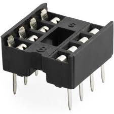
8-pin sockets

Printed circuit
Download gerber file Gerber_servo_555_pcb
SUBSCRIBE TO OUR NEWSLETTERS, RECEIVE IN YOUR EMAIL THE MOST OUTSTANDING NEWS, JUST BY ENTERING YOUR EMAIL
[wysija_form id=”1″]
RECOMMENDED PROJECT