
In this tutorial we will see how to make a breathalyzer, simple economical and easy to make. We’ll see the source code, the circuit assembly all step by step. The printed circuit board will be available for free.
What is a breathalyzer?
It is a device to measure the amount of alcohol present in the air breathed by a person, it can also measure the amount of alcohol contained in a liquid or gas.
MQ3 module
This alcohol sensor is suitable for detecting the concentration of alcohol in your breath, just like a commercial breathalyzer. It has a high sensitivity and fast response time. The sensor features a resistive analog output based on alcohol concentration.
Some comments from the MQ3 sensor
This sensor has 4 pins two of which are power, one is an analog output (PIN AD) and the other a digital output (PIN DO), it is finally possible to regulate its sensitivity, by means of a potentiometer that owns the board, they will notice that when you turn on this module and connect a LED it is turned on, since this output is reversed or denied (NOT). This means that in the presence of alcohol in the sensor the LED will be on and if it exceeds the set threshold with the potentiometer it will turn off. This is very useful if we do not want to use any microcontroller, nor Arduino, with this module we can only have a very simple breathalyzer just feeding the module and nothing else.
As soon as we turn on this module, it will start to heat up, we have to wait a few minutes (about 5) for the module to heat up and we have a correct census.
You may be interested in projects in Arduino, pic, robotics, telecommunications, subscribe http://www.youtube.com/user/carlosvolt?sub_confirmation=1 videos with full source code and diagrams

Electronic components
An Arduino nano
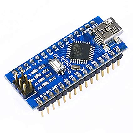
The Arduino Nano is a small board, complete and compatible with the test board based on the ATmega328 (Arduino Nano 3.x). It has about the same functionality as the Arduino Duemilanove, but in a different package. It only lacks a DC power connector and works with a Mini-B USB cable instead of a standard one.
| Microcontroller | ATmega328 |
| Architecture | Avr |
| Operating voltage | 5 V |
| Flash memory | 32 KB of which 2 KB uses the bootloader |
| Sram | 2 KB |
| Clock speed | 16 MHz |
| Analog pins IN | 8 |
| Eeprom | 1 KB |
| DC current by I/O pins | 40 mA (I/O pins) |
| Input voltage | 7-12 V |
| Digital I/O Pins | 22 (6 of which are PWM) |
| PWM output | 6 |
| Energy consumption | 19 mA |
| PCB size | 18 x 45 mm |
| Weight | 7g |
Pin diagram

A buzzer

Four female pins

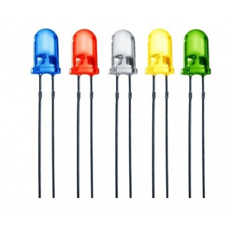
Six 5mm led diodes of different colors
Sensor MQ3

Description
MQ3 Alcohol Concentration Sensor Module
Overview
This sensor detects the concentration of alcohol in the air. It simply connects to an analog input of a microcontroller like Arduino and we can measure the concentration of alcohol.
It has an analog output that indicates the concentration of alcohol in the environment
(the higher the output level, the higher the gas concentration) and also has a digital output that drops to 0 when the alcohol concentration exceeds the preset level.
Ideal article for use with Arduino boards or any microcontroller (PIC, AVR, FREESCALE, etc.)
Specifications
Operating Voltage: 5Vdc Integrated
LM393 amplifier with variable gain by potentiometer.
2 output pins (analog output and TTL level output).
Valid low-level TTL level output, can be connected directly to the microcontroller.
Analog output of 0 x 5 V , the highest voltage equals a higher concentration.
Working conditions: Ambient temperature:-10oC to 65oC, Humidity:-95% RH
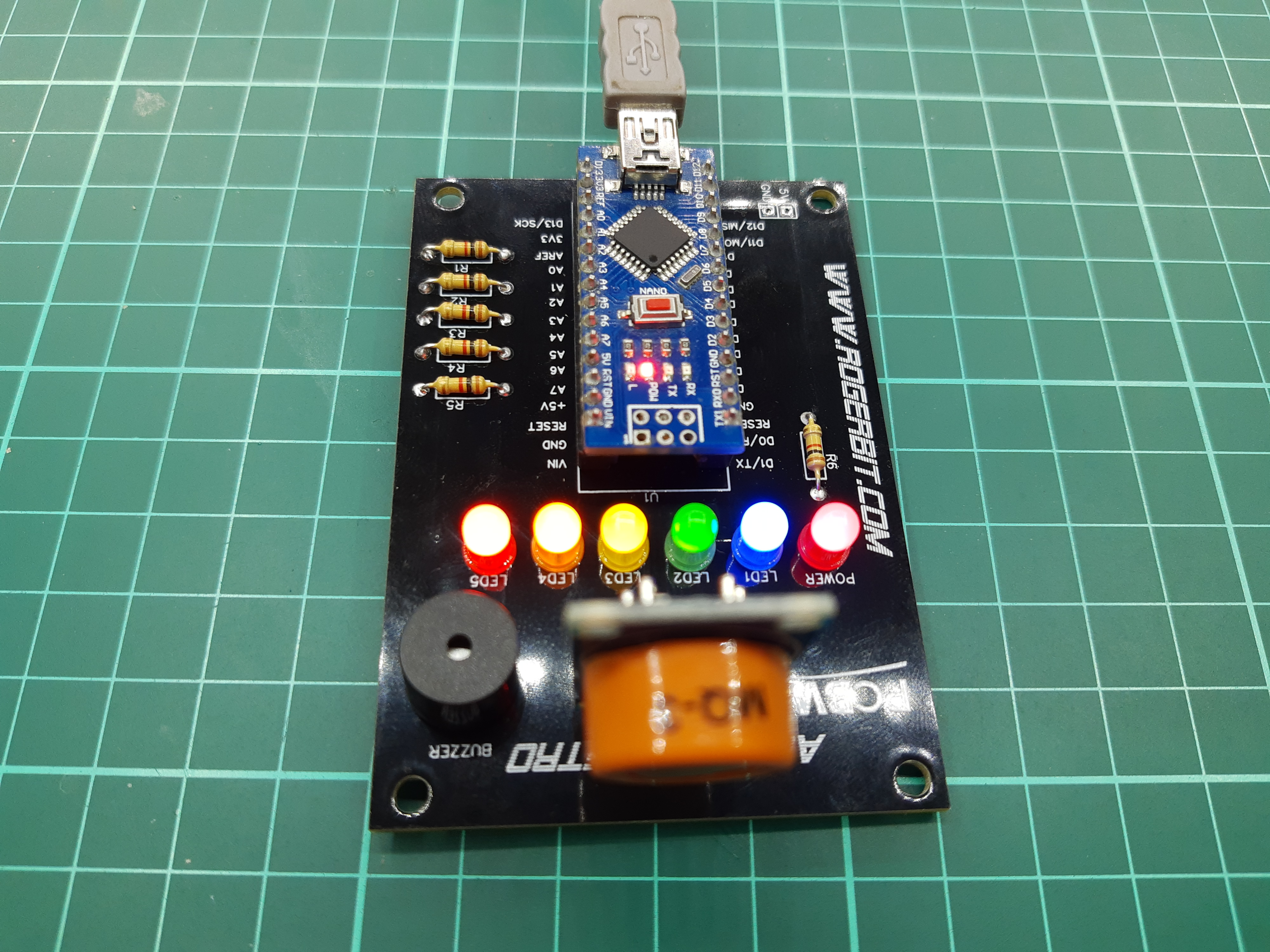
Pcb
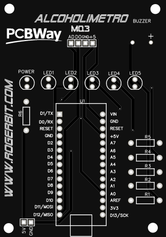
Download gerber file –> Gerber_ALCOHOLIMETRO
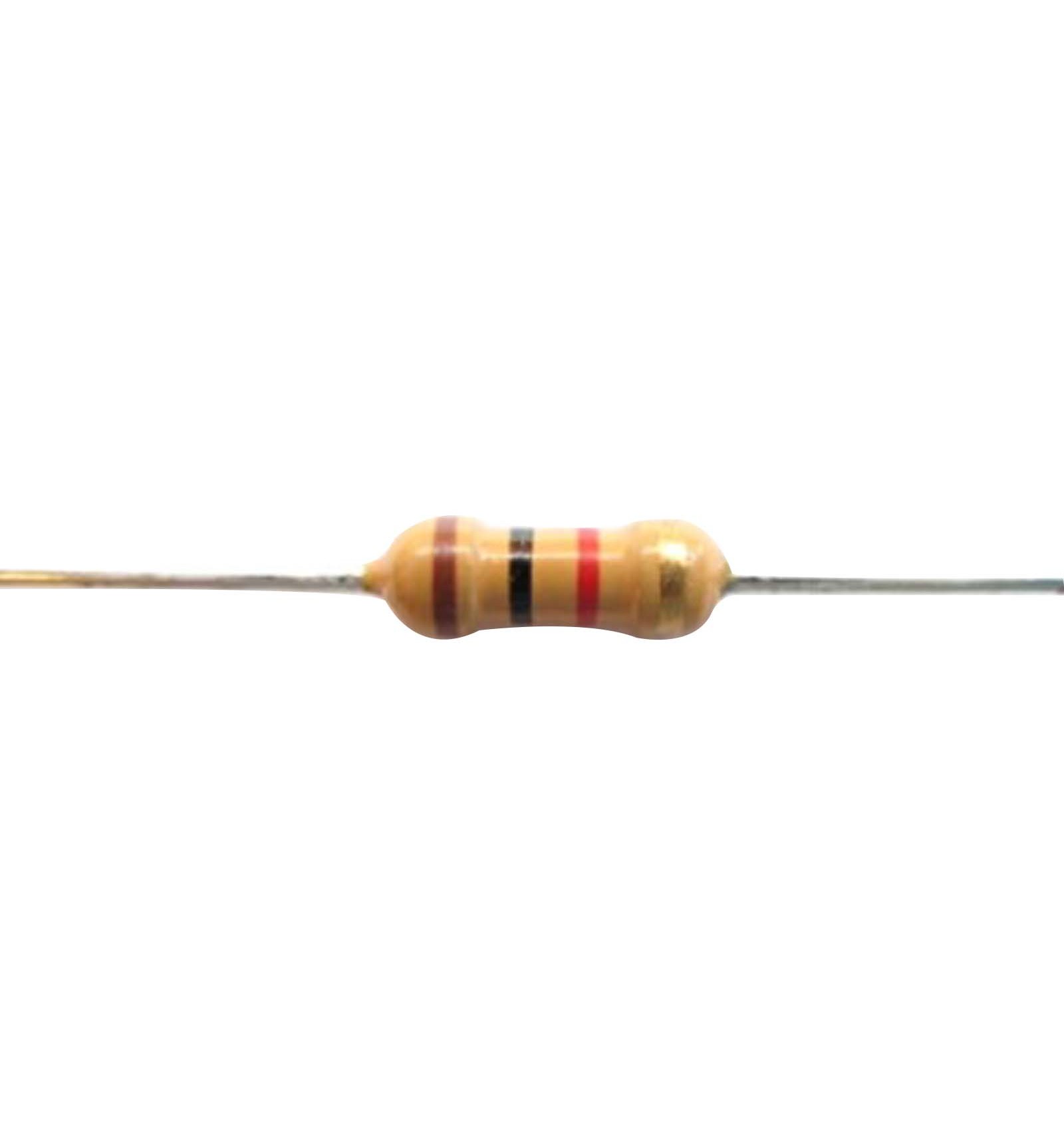
Six 1 Kohm resistors
A socket for Arduino nano

Source
|
1 2 3 4 5 6 7 8 9 10 11 12 13 14 15 16 17 18 19 20 21 22 23 24 25 26 27 28 29 30 31 32 33 34 35 36 37 38 39 40 41 42 43 44 45 46 47 48 49 50 51 52 53 54 55 56 57 58 59 60 61 62 63 64 65 66 67 68 69 70 71 72 73 74 75 76 77 78 79 80 81 82 83 84 85 86 87 88 89 90 91 92 93 94 95 96 |
int sensor=0; void setup(){ Serial.begin(9600);//Configuración de la velocidad del puerto serial de arduino //Se configuraran los pines 2,3,4,5,6 y 7 como salidas //Del pin 2 al 6 van conectados a diodos led con su respectiva resistencia pinMode(2, OUTPUT); pinMode(3, OUTPUT); pinMode(4, OUTPUT); pinMode(5, OUTPUT); pinMode(6, OUTPUT); pinMode(7, OUTPUT);//Va conectado al Buzzer sensor=analogRead(A0);//Se lee el valor de la entrada analógica A0 while(sensor>100){ Serial.print("Esperando a que se estabilice el sensor (valor menor a 100): ");//Se imprime su valor por el terminal serial sensor=analogRead(A0);//Se lee el valor de la entrada analógica A0 Serial.println(sensor);//Se imprime su valor por el terminal serial digitalWrite(2, HIGH); digitalWrite(3, HIGH); digitalWrite(4, HIGH); digitalWrite(5, HIGH); digitalWrite(6, HIGH); delay(500); digitalWrite(2, LOW); digitalWrite(3, LOW); digitalWrite(4, LOW); digitalWrite(5, LOW); digitalWrite(6, LOW); delay(500); } } void loop(){ sensor=analogRead(A0);//Se lee el valor de la entrada analógica A0 Serial.print("Valor del sensor: "); Serial.println(sensor);//Se imprime su valor por el terminal serial //Se compara el valor de la variable sensor si se cumple apagará todos los led if(sensor<99){ digitalWrite(2, LOW); digitalWrite(3, LOW); digitalWrite(4, LOW); digitalWrite(5, LOW); digitalWrite(6, LOW); digitalWrite(7, LOW); } //Se compara el valor de la variable sensor si se cumple encenderá el led en el pin 2 if(sensor>100){ digitalWrite(2, HIGH); digitalWrite(3, LOW); digitalWrite(4, LOW); digitalWrite(5, LOW); digitalWrite(6, LOW); digitalWrite(7, LOW); } //Se compara el valor de la variable sensor si se cumple encenderá el led en el pin 2 y 3 if(sensor>200){ digitalWrite(2, HIGH); digitalWrite(3, HIGH); digitalWrite(4, LOW); digitalWrite(5, LOW); digitalWrite(6, LOW); digitalWrite(7, LOW); } //Se compara el valor de la variable sensor si se cumple encenderá el led en el pin 2, 3 y 4 if(sensor>300){ digitalWrite(2, HIGH); digitalWrite(3, HIGH); digitalWrite(4, HIGH); digitalWrite(5, LOW); digitalWrite(6, LOW); digitalWrite(7, LOW); } //Se compara el valor de la variable sensor si se cumple encenderá el led en el pin 2, 3, 4, y 5 if(sensor>350){ digitalWrite(2, HIGH); digitalWrite(3, HIGH); digitalWrite(4, HIGH); digitalWrite(5, HIGH); digitalWrite(6, LOW); digitalWrite(7, LOW); } //Se compara el valor de la variable sensor si se cumple encenderá el led en el pin 2, 3 ,4 ,5, 6 y el buzzer if(sensor>400){ digitalWrite(2, HIGH); digitalWrite(3, HIGH); digitalWrite(4, HIGH); digitalWrite(5, HIGH); digitalWrite(6, HIGH); digitalWrite(7, HIGH);//Se actica el buzzer } delay(100);//pequeño retardo antes de comenzar de vuelta } |

SUBSCRIBE TO OUR NEWSLETTERS, RECEIVE IN YOUR EMAIL THE MOST OUTSTANDING NEWS, JUST BY ENTERING YOUR EMAIL
[wysija_form id=”1″]
RECOMMENDED PROJECT