
In this tutorial, we’ll look at how to make a low-cost audio amplifier with the lm386 integrated circuit. We will look at the list of electronic materials and components, also the assembly of the board step by step and talk about some features of the lm386 integrated circuit. The printed circuit board is included completely free of charge.
You may be interested in projects in Arduino, pic, robotics, telecommunications, subscribe http://www.youtube.com/user/carlosvolt?sub_confirmation=1 videos with full source code and diagrams

Overview
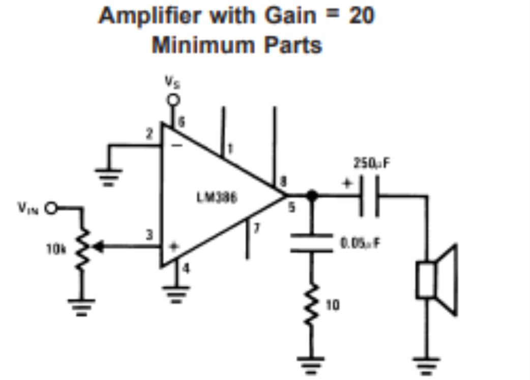
The LM386 is a power amplifier designed for use in low voltage consumption applications. The gain is set internally to 20 to keep the external parts count low, but the addition of a resistor and capacitor between pins 1 and 8 will increase the gain to any value up to 200.
The inputs are ground-referenced while the output is automatically polarized to half the supply voltage. The power consumption at rest is only 24 milliwatts when operating from a 6 volt supply, making the LM386 ideal for battery operation.
Features
- Battery operation
- Minimum external parts
- Wide voltage supply range: 4V – 12V or 5V – 18V
- Low standby current consumption: 4 mA
- Voltage gains from 20 to 200
- Ground-reference entry
- Self-centering output quiescent voltage
- Low distortion
- Available in 8-pin MSOP package
Applications
- AM-FM radio amplifiers
- Portable tape player amplifiers
- Intercoms
- TV sound systems
- line controllers
- Ultrasonic controllers
- Small servo controllers
- Power Converters
Electronic diagram

LM386
The LM386 (also known as JRC386) is an integrated circuit consisting of an amplifier that requires low voltage, both in audio input and power. It is often used in amplifiers for computers (speakers), radios, guitar amplifiers, etc. Supplying 9 volts on pin 8 you can get 0.5 W of power, with only 0.2% distortion.
The TDA2822 shares several features of this integrated, works in stereo and is also used in the same class of electronics.
It is also a very used circuit to make home audio amplifiers.
Application Tips Gain
Control To make
the LM386 a more versatile amplifier, two pins (1 and 8) are provided for gain control. With pins 1 and 8 open, the resistance of 1.35 ko sets the gain to 20 (26 dB). If a capacitor is set from pin 1 to 8, without going through the resistance of 1.35 k, the gain will increase to 200 (46 dB). If a resistor is placed in series with the capacitor, the
gain can be adjusted to any value from 20 to 200. Gain control can also be performed by capacitively attaching a resistance (or FET) from pin 1 to ground.
Additional external components can be placed in parallel with internal feedback resistors to adapt gain and frequency response for individual applications. For example, we can compensate for a poor bass response of the speakers by shaping the frequency of the feedback path. This is done with an RC series of pin 1 to 5 (in parallel with the internal resistance of 15 ko).
For effective bass reinforcement of 6 dB: R ≅ 15 k, the lowest value for stable good performance is R s 10 k s if pin 8 is open. If pins 1 and 8 are omitted, then R can be used as low as 2 ko. This restriction is because the amplifier is only compensated for closed loop gains greater than 9.
INPUT BIASING The
scheme shows that both inputs are ground polarized with a resistance of 50 ko. The base current of the input transistors is approximately 250 nA, so the inputs are approximately 12.5 mV when left open. If the resistance of the DC source that drives the LM386 is greater than 250 k, it will provide very little offset (approximately 2.5 mV at the input, 50 mV at the output). If the DC source resistance is less than 10 k, then unused grounding will keep the compensation low approximately 2.5 mV at the input, 50 mV at the output). For DC source resistors between these values we can eliminate excess compensation by placing an unused input resistance to ground, equal in value to the resistance of the cd source. Of course, all compensation issues are eliminated if the input is coupled capacitively.
When using the LM386 with higher gains (without going through Resistance of 1.35 ko between pins 1 and 8) it is necessary to omit the unused input, avoiding gain degradation and possible instability. This is done with a capacitor of 0.1 F or a short ground depending on the resistance of the DC source at the driven input.
Typical applications


Materials
A 1K resistor

4.7uF capacitor

Un resistor de 10K

A 10 Ohm resistor

Two 470uF capacitors

A 47nF capacitor

An LM386 integrated circuit

Male pin strip

A 10k potentiometer

An 8-legged plinth

Pcb

Download gerber file –> Amplifier with lm386
⭐️ SUBSCRIBE: https://www.youtube.com/user/carlosvolt?sub_confirmation=1 (Don’t forget to activate the 🔔)
👉Secondary channel: https://www.youtube.com/channel/UCjES9aB4g1F3IQbAk2nWCZg
👉Instagram: https://www.instagram.com/carlosvolt_electronic_robotic/
👉Tik Tok: https://www.tiktok.com/@carlosvolt
👉Fanpage: https://www.facebook.com/rogerbitfanpage/
👉Facebook: https://www.facebook.com/groups/RogerBit
👉Twitter: https://twitter.com/rogerbit_
👉Donations by paypal https://goo.gl/824Dnm or donacion@rogerbit.com
👉Website: https://www.rogerbit.com
SUBSCRIBE TO OUR NEWSLETTERS, RECEIVE IN YOUR EMAIL THE MOST OUTSTANDING NEWS, JUST BY ENTERING YOUR EMAIL
[wysija_form id=”1″]
RECOMMENDED PROJECT