
In this tutorial we will see how to make an automatic fish feeder with arduino nano, a 28byj-48 stepper motor with its respective controller. In addition, a real-time PSTN or clock is included, ds1307 although it also serves the ds3231, which will allow us to configure the system to do the food download at the scheduled time, it includes the source code, the gerber file, the stl files to print the feeder, all totally free as always.
You may be interested in projects in Arduino, pic, robotics, telecommunications, subscribe http://www.youtube.com/user/carlosvolt?sub_confirmation=1 videos with full source code and diagrams

Circuit
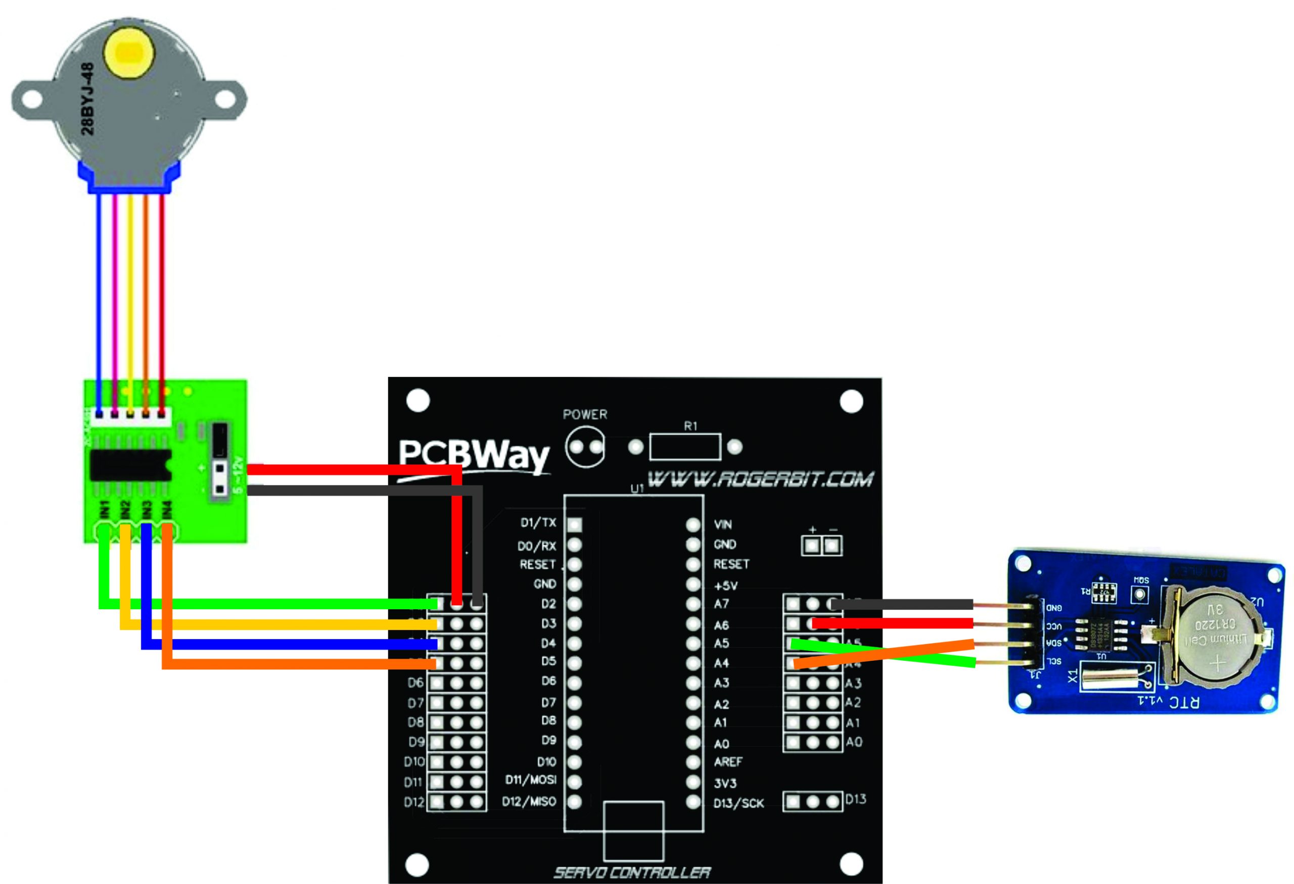
We will use pins 2, 3, 4 and 5 for stepper motor control, and A4 pins with the SDA pin of the PSTN module, and pin A5 with PSTN SCL.
Materials
An Arduino nano

The Arduino Nano is a small board, complete and compatible with the test board based on the ATmega328 (Arduino Nano 3.x). It has about the same functionality as the Arduino Duemilanove, but in a different package. It only lacks a DC power connector and works with a Mini-B USB cable instead of a standard one.
| Microcontroller | ATmega328 |
| Architecture | Avr |
| Operating voltage | 5 V |
| Flash memory | 32 KB of which 2 KB uses the bootloader |
| Sram | 2 KB |
| Clock speed | 16 MHz |
| Analog pins IN | 8 |
| Eeprom | 1 KB |
| DC current by I/O pins | 40 mA (I/O pins) |
| Input voltage | 7-12 V |
| Digital I/O Pins | 22 (6 of which are PWM) |
| PWM output | 6 |
| Energy consumption | 19 mA |
| PCB size | 18 x 45 mm |
| Weight | 7g |
Pin diagram

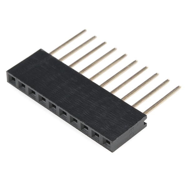
Female pins
A LED

A 28byj-48 stepper motor with its controller

The parameters of this stepper motor are:
- Model: 28BYJ-48 – 5V
- Nominal voltage: 5V (or 12 V, value indicated on the rear).
- Number of phases: 4.
- Speed reducer: 1/64
- Pass angle: 5,625o / 64
- Frequency: 100Hz
- DC Resistance: 50o ±7 % (25oC)
- Traction frequency: > 600Hz
- Traction-free frequency: > 1000Hz
- Torque with traction: >34.3mN.m (120Hz)
- Self-position torque: >34.3mN.m
- Torque with friction: 600-1200 gf.cm
- Drag in torque: 300 gf.cm
- Insulation Resistance > 10M (500V)
- Electrically ingilised: 600VAC/1mA/1s
- Degree of ingesting: A
- Temperature increase: < 40K (120Hz)
- Noise: < 35dB (120Hz, no charge, 10cm)
ULN2003APG

Main specifications:
- 500 mA rated collector current (single output)
- 50 V output (there is a version that supports 100 V output)
- Includes output return diodes
- Inputs compatible with TTL and 5-V CMOS logic
Male pins

A 1 Kohm resistor

A module rtc ds1307

Description
The PSTN module is based on the high-precision, real-time DS1307 clock module.
Through the I2C interface to communicate with singlechip, you can read year, month, day, week, hour, minute, second, you can read up to 2100.
The Control interface is I2C.
Recommended voltage: cc 5 V, the module direction is 0x68, the Control interface level is 5
V or 3.3 V. The DS1307 series real-time clock (RTC) is a low power full binary code (BCD) decimal code decimal time /calendar.
Plus 56 bytes of NV SRAM. Address and data are transferred in series via an I2C, two-way bus.
The clock/calendar provides seconds, minutes, hours, day, date, month and year information. The end of the month date is automatically adjusted for months with less than 31 days, including year-to-year jump corrections. The clock works in 24 hours or 12 hour format with AM/PM indicator. The DS1307
has a built-in power sensing circuit that detects power failures and automatically switches to the backup supply.
The timing operation continues while the part operates from the backup supply.
Features
VCC supply voltage specification: 4.5 x 5.5 V;
Battery Voltage: 3.5V x 2.0; H
Igh level input: 2.1 vvcc + 0.3 V;
Low-level input:-0.3 x + 0.8 V;
Control Interface: 4-pin (GND, VCC, SDA, SCL), GND for ground wire, VCC for power supply, SDA for I2C interface data cable, SCL for I2C interface clock cable;
Real-time IC: DS1307Z; Independent synchronization: Through the I2C interface they communicate with MCU.
Battery: CR1220 battery;
Hole installed: 4m2 screw hole, diameter hole: 2.2mm, easy to install.
A socket for the Arduino nano

Printed circuit (pcb)

Gerber file –> MULTIPLES SERVOS
STL files
Source
Remember to install the Adafruit RTClib.h library, and to avoid any incompatibility, I recommend installing the version in the image.

|
1 2 3 4 5 6 7 8 9 10 11 12 13 14 15 16 17 18 19 20 21 22 23 24 25 26 27 28 29 30 31 32 33 34 35 36 37 38 39 40 41 42 43 44 45 46 47 48 49 50 51 52 53 54 55 56 57 58 59 60 61 62 63 64 65 66 67 68 69 70 71 72 73 74 75 76 77 78 79 80 81 82 83 84 85 86 87 88 89 90 91 92 93 94 95 |
#include <Wire.h> #include "RTClib.h" bool estado = false; int diasSemana; // Pines para controlar el motor paso a paso #define IN1 2 #define IN2 3 #define IN3 4 #define IN4 5 // Secuencias del motor paso a paso int paso [4][4] = { {1, 1, 0, 0}, {0, 1, 1, 0}, {0, 0, 1, 1}, {1, 0, 0, 1} }; //Elegimos el tipo de módulo RTC RTC_DS1307 rtc; //RTC_DS3231 rtc; void setup() { Serial.begin(9600); // Todos los pines como salida pinMode(IN1, OUTPUT); pinMode(IN2, OUTPUT); pinMode(IN3, OUTPUT); pinMode(IN4, OUTPUT); delay(1000); //Inicializamos el módulo rtc if (!rtc.begin()) { Serial.println(F("No se pudo encontrar el RTC")); while (1); } //Ajuste automático de la fecha y hora, según la hora de tu pc // rtc.adjust(DateTime(F(__DATE__), F(__TIME__))); //Ajuste manual de la fecha y hora rtc.adjust (DateTime (2021, 3, 6, 22, 59, 55)); } // Comprobar si esta programado el encendido bool encendidoProgramado(DateTime date) { diasSemana = date.dayOfTheWeek(); float hours = date.hour() + date.minute() / 60.0; // Programamos la hora de activación bool horaActivacion = ((hours >= 20.00 && hours < 23.50)); // Programamos los días de la semana para la activación, en este caso todos los días de la semana bool diaActtivacion = (diasSemana == 0 || diasSemana == 1 || diasSemana == 2 || diasSemana == 3 || diasSemana == 4 || diasSemana == 5 || diasSemana == 6 ); if (horaActivacion && diaActtivacion) { Serial.println("Encendido programado"); return true; } return false; } void loop() { //Muestra la fecha y hora en el monitor serial DateTime now = rtc.now(); Serial.print("Fecha: "); Serial.print (now.day (), DEC); Serial.print ('/'); Serial.print (now.month (), DEC); Serial.print ('/'); Serial.print(now.year (), DEC); Serial.print (" Hora: "); //Serial.print ("--"); Serial.print (now.hour (), DEC); Serial.print (':'); Serial.print (now.minute (), DEC); Serial.print (':'); Serial.print (now.second (), DEC); Serial.println (); if (estado == false && encendidoProgramado(now)) { estado = true; //Movemos el motor paso a paso algunos grados for (int m = 0; m < 51; m++){ for (int p = 0; p < 4; p++) { digitalWrite(IN1, paso[p][0]); digitalWrite(IN2, paso[p][1]); digitalWrite(IN3, paso[p][2]); digitalWrite(IN4, paso[p][3]); delay(2); } } } else if (estado == true && !encendidoProgramado(now)) { estado = false; Serial.println("Tiempo cumplido"); } delay(1000); } |
You may be interested in projects in Arduino, pic, robotics, telecommunications, subscribe http://www.youtube.com/user/carlosvolt?sub_confirmation=1 videos with full source code and diagrams
RECOMMENDED PROJECT