
In this tutorial we will see how to make a system that allows us to turn on lights with telegram, from anywhere in the world, just by typing a command. To do this a dual channel relay module will turn on two 110V/220V bulbs, the esp32 will connect to our Wifi network and by means of commands, to control the on or off of lights. We will send messages through the telegram messaging service, where the bot will respond to us when the light is turned on or off and we will also be able to know the status of each of them.
You may be interested in projects in Arduino, pic, robotics, telecommunications, subscribe http://www.youtube.com/user/carlosvolt?sub_confirmation=1 videos with full source code and diagrams

Circuit

Electronic components
Cables dupont

An ESP32
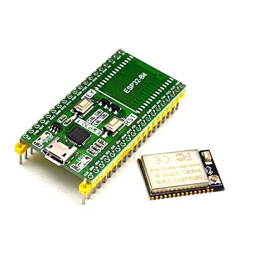
Features of the ESP32-T module

Connectivity
The ESP32 module has all the wiFi variants:
- 802.11 b/g/n/e/i/n
- Wi-Fi Direct (P2P), P2P Discovery, P2P Group Owner mode and P2P Power Management
This new version includes low-power Bluethoot connectivity
- Bluetooth v4.2 BR/EDR and BLE
- BLE Beacon
In addition, you can communicate using SPI, I2C, UART, MAC Ethernet, Host SD protocols
Microcontroller features
The CPU consists of a Tensilica LX6 Model SoC with the following features and memory
- Dual 32-bit core with 160MHz speed
- 448 kBytes ROM
- 520kByteS SRAM
Have 48 Pins
- 18 12-bit ADC
- 2 8-bit DAC
- 10 pin contact sensors
- 16 PWM
- 20 Digital inputs/outputs
Power and consumption modes
For proper operation of the ESP32 it is necessary to supply a voltage between 2.8V and 3.6V. The energy you consume depends on the mode of operation. It contains a mode, the Ultra Low Power Solution (ULP),in which basic tasks (ADC, PSTN…) continue to be performed in Sleep mode.
Two spotlights

A pcb

Gerber file
Pines macho

Dual-channel relay module

Features
- Card with 2-5V and 2-channel relays
- Tical current: 4mA
- Activation current: 2mA
- Working current: 65mA
- High Current Relay: AC250V 10A; DC30V 10A.
- Standard interface for microcontroller: Arduino, AVR, PIC, DSP, ARM, etc.
- PC817 on-board optocoupler with anti-jamming optical isolation capability
- Independent contact wiring, safe and reliable
- With screw holes for easy installation
- Size: 44.4×32.4mm
Pinout
Input Part:
- VCC: connect to positive power (depending on relay voltage range)
- GND: connect to negative power
- IN1: channel trigger pin 1 relay module (high level trigger)
- IN2: channel trigger pin 2 relay module (high level trigger)
Output Part:
- Normally open (NA): Normally open relay pin. NO pin is not connected to COM pin when relay is off. The pin does NOT connect to the COM pin when the relay is on.
- Pin común (COM): pin común del relé.
- Normally closed (NC): normally closed relay pin. The NC pin connects to the COM pin when the relay is off. The NC pin does not connect to the COM pin when the relay is on.
A plinth for the esp32

Source
|
1 2 3 4 5 6 7 8 9 10 11 12 13 14 15 16 17 18 19 20 21 22 23 24 25 26 27 28 29 30 31 32 33 34 35 36 37 38 39 40 41 42 43 44 45 46 47 48 49 50 51 52 53 54 55 56 57 58 59 60 61 62 63 64 65 66 67 68 69 70 71 72 73 74 75 76 77 78 79 80 81 82 83 84 85 86 87 88 89 90 91 92 93 94 95 96 97 98 99 100 101 102 103 104 105 106 107 108 109 110 111 112 113 114 115 116 117 118 119 120 121 122 123 124 125 126 127 128 129 130 131 132 133 134 135 136 137 138 139 |
#include <WiFi.h> #include <WiFiClientSecure.h> #include <UniversalTelegramBot.h> // Reemplazar con los datos de tu red wifi #define WIFI_SSID "Tu_red_wifi" #define WIFI_PASSWORD "Tu_clave" //Token de Telegram BOT se obtenienen desde Botfather en telegram #define BOT_TOKEN "Tu_token" const unsigned long tiempo = 1000; //tiempo medio entre mensajes de escaneo WiFiClientSecure secured_client; UniversalTelegramBot bot(BOT_TOKEN, secured_client); unsigned long tiempoAnterior; //última vez que se realizó el análisis de mensajes const int led12 = 12; const int led14 = 14; int estadoLed12 = 0; int estadoLed14 = 0; int inicio = 1; String chat_id; #define ID_Chat "tu_id_chat"//ID_Chat se obtiene de telegram void mensajesNuevos(int numerosMensajes) { for (int i = 0; i < numerosMensajes; i++) { String chat_id = bot.messages[i].chat_id; String text = bot.messages[i].text; //////////Luz 1 en el pin 12////// if (text == "Luz1on") { digitalWrite(led12, LOW); // estadoLed12 = 1; bot.sendMessage(chat_id, "Luz 1 encendida", ""); } if (text == "Luz1off") { estadoLed12 = 0; digitalWrite(led12, HIGH); // bot.sendMessage(chat_id, "Luz 1 apagada", ""); } //////////Luz 2 en el pin 14////// if (text == "Luz2on") { digitalWrite(led14, LOW); estadoLed14 = 1; bot.sendMessage(chat_id, "Luz 2 encendida", ""); } if (text == "Luz2off") { estadoLed14 = 0; digitalWrite(led14, HIGH); bot.sendMessage(chat_id, "Luz 2 apagada", ""); } ////////Estado de las luces /////// if (text == "Estado") { ////Estado luz 1//// if (estadoLed12) { bot.sendMessage(chat_id, "Luz 1 encendida", ""); } else { bot.sendMessage(chat_id, "Luz 1 apagada", ""); } ////Estado luz 2//// if (estadoLed14) { bot.sendMessage(chat_id, "Luz 2 encendida", ""); } else { bot.sendMessage(chat_id, "Luz 2 apagada", ""); } } if (text == "Ayuda") { String ayuda = "Bienvenido al sistema de control luces con Esp32, " ".\n"; ayuda += "Estas son tus opciones.\n\n"; ayuda += "Luz1on: para encender la Luz 1 \n"; ayuda += "Luz1off: para apagar la luz 1 \n"; ayuda += "Luz2on: para encender la Luz 2 \n"; ayuda += "Luz2off: para apagar la luz 2 \n"; ayuda += "Estado : devuelve el estado actual de las luces\n"; ayuda += "Ayuda: Imprime este menú \n"; ayuda += "Recuerda el sistema distingue entre mayuculas y minusculas \n"; bot.sendMessage(chat_id, ayuda, ""); } } } void setup() { Serial.begin(115200); pinMode(led12, OUTPUT); //inicializar pin 12 digital como salida. pinMode(led14, OUTPUT); //inicializar pin 14 digital como salida. digitalWrite(led12, HIGH); // digitalWrite(led14, HIGH); // Intenta conectarse a la red wifi Serial.print("Conectando a la red "); Serial.print(WIFI_SSID); WiFi.begin(WIFI_SSID, WIFI_PASSWORD); secured_client.setCACert(TELEGRAM_CERTIFICATE_ROOT); //Agregar certificado raíz para api.telegram.org while (WiFi.status() != WL_CONNECTED) { Serial.print("."); delay(500); } Serial.print("\nConectado a la red wifi. Dirección IP: "); Serial.println(WiFi.localIP()); if(inicio == 1){ Serial.println("Sistema preparado"); bot.sendMessage(ID_Chat, "Sistema preparado!!!, escribe Ayuda para ver las opciones", "");//Enviamos un mensaje a telegram para informar que el sistema está listo inicio = 0; } } void loop() { //Verifica si hay datos nuevos en telegram cada 1 segundo if (millis() - tiempoAnterior > tiempo) { int numerosMensajes = bot.getUpdates(bot.last_message_received + 1); while (numerosMensajes) { Serial.println("Comando recibido"); mensajesNuevos(numerosMensajes); numerosMensajes = bot.getUpdates(bot.last_message_received + 1); } tiempoAnterior = millis(); } } |
Download Library –> Universal-Arduino-Telegram-Bot-master
Create Bot on Telegram

In telegram we look for BotFather

We write /start and something similar to this will appear to us

Write /newbot
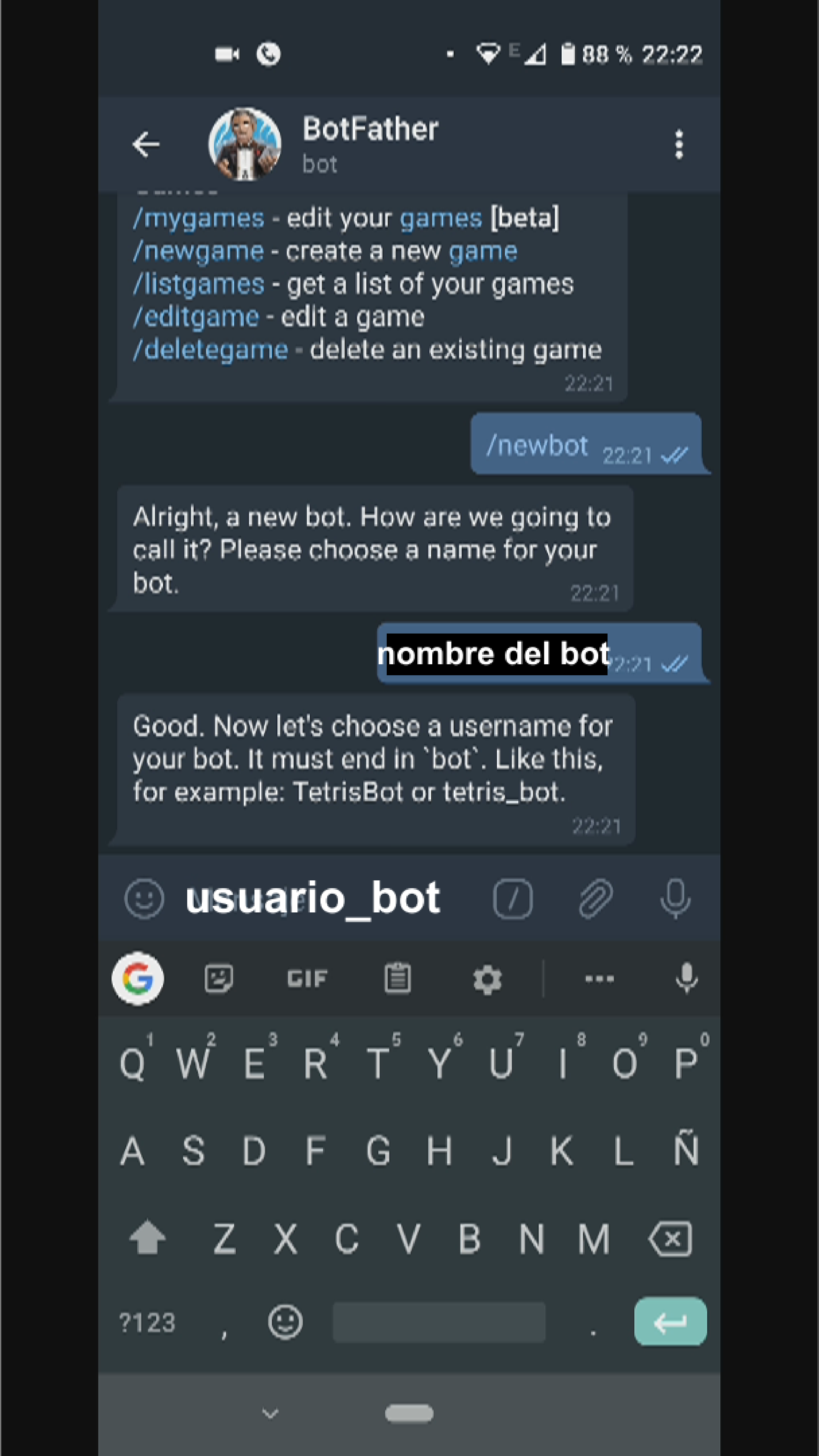
I will see the name of the bot, and we invent a name for our bot, it must be in the format «usuario_bot»

We’ll get a token that we’re going to use in the source code

Now we’ll look for IDBot, and we’ll start it

We write /getid and it will give us user_id that we should place in the source code
SUBSCRIBE TO OUR NEWSLETTERS, RECEIVE IN YOUR EMAIL THE MOST OUTSTANDING NEWS, JUST BY ENTERING YOUR EMAIL
[wysija_form id=”1″]
RECOMMENDED PROJECT