
In this tutorial we will put together a dual light ignition system, since we can control the ignition and paid by means of an infrared remote control, and also by means of 8 pushbuttons. We will use an 8-channel relay module, an arduino nano, an infrared receiver module, a pcb made of pcbway, and other electronic components. We will assemble the circuit, step by step analyze the source code and finally test all the operation of the system.
You may be interested in projects in Arduino, pic, robotics, telecommunications, subscribe http://www.youtube.com/user/carlosvolt?sub_confirmation=1 videos with full source code and diagrams

materials
An Arduino nano

The Arduino Nano is a small board, complete and compatible with the test board based on the ATmega328 (Arduino Nano 3.x). It has about the same functionality as the Arduino Duemilanove, but in a different package. It only lacks a DC power connector and works with a Mini-B USB cable instead of a standard one.
| microcontroller | ATmega328 |
| architecture | AVR |
| Operating voltage | 5 V |
| Flash memory | 32 KB of which 2 KB uses the bootloader |
| Sram | 2 KB |
| Clock speed | 16 MHz |
| Analog pins IN | 8 |
| Eeprom | 1 KB |
| DC current by I/O pins | 40 mA (I/O pins) |
| Input voltage | 7-12 V |
| Digital I/O Pins | 22 (6 of which are PWM) |
| PWM output | 6 |
| Energy consumption | 19 mA |
| PCB size | 18 x 45 mm |
| weight | 7g |
Pin diagram

Female pins
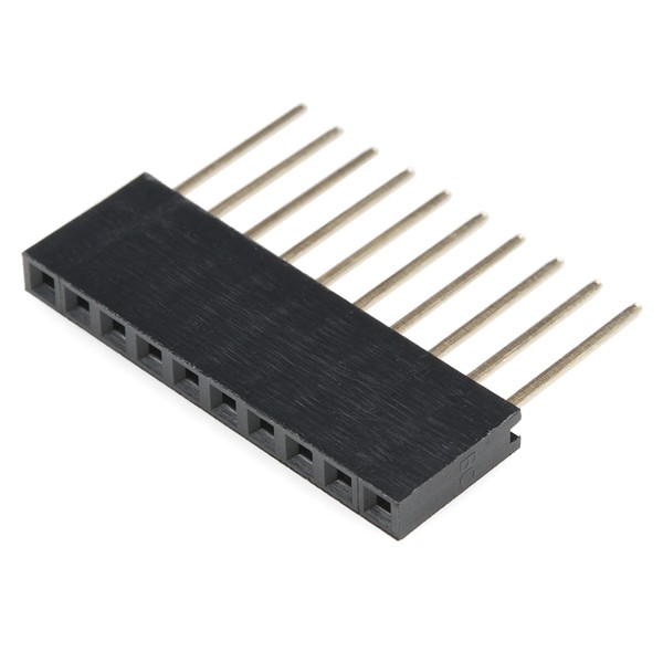
A socket for the Arduino nano

8-channel relay module

characteristics
Controls the on/off of high-powered equipment (appliances). Works perfectly with Arduino, Pic or any other digital system.
Within the wide variety of projects that we can carry out with Arduino, we may want to control high voltage or high amperage components, such as bulbs or water pumps, which cannot be handled directly with Arduino. In these cases it is necessary to use Relays or Reles, these devices allow to control high voltage loads with a small signal.
The module has 8 high quality relays, capable of handling loads up to 250V/10A. Each channel has electrical insulation by means of an optocoupler and a status indicator LED. Its design makes it easy to work with Arduino, as with many other systems such as Raspberry Pi, ESP8266 (NodeMCU and Wemos), Teensy and Pic. This Relay module activates the normally open output (NO: Normally Open) when receiving a logical “0” (0 Volts) and deactivates the output with a logical “1” (5 volts). For Arduino and Relays programming it is recommended to use timers with the “millis()” function and therefore not use the “delay” function that prevents the system from continuing to work while a relay is on/off.
Among the loads that can be handled we have: light bulbs, luminaires, AC motors (220V), DC motors, solenoids, solenoid valves, water heaters and a wide variety of other actuators. It is recommended to perform and verify connections before powering the circuit, it is also a good practice to protect the circuit within a case.
Technical data
8 independent channels
8 1-pole relays 2 shots
Relay coil voltage is 5 VDC
Led indicator for each channel (lights when relay coil is active)
Current-activated: the control circuit must provide a current of 15 to 20 mA
Can be directly controlled by logical circuits
Screw connection terminals (clemas)
Logical signal input terminals with 0.1″ male headers.
Can be directly controlled by logical circuits
Food and consumption
The easiest way to power this module is from Vcc and GND of the Arduino board, keeping the Jumper in place, so JD-Vcc Vcc. This connection has two important limitations:
The electrical switching provided by optocouplers is lost, increasing the chance of damage to the Arduino if there is a problem with relay loads.
The current consumed by the relay coils must be provided by the Arduino board. Each coil consumes about 90 mA and the four joints add up to 360 mA. If we add to this the consumptions that other outputs can have, we are very close to the 500 mA that a USB port can supply. In this case the Arduino should be fed with an external source, which increases the current limit to 1 A (in the case of the Arduino UNO).
The safest way is to remove the jumper and power the relay board with two sources: that of the Arduino board connected to Vcc and a second source, with the positive to JD-Vcc and the negative to GND, without being attached to the Arduino board. This connection has as advantages:
There is complete ingessation between the load and the Arduino.
All relay consumption is taken from the second source and not from the Arduino or USB port.
Tickets
The inputs to the board can be connected directly to the digital outputs of the Arduino board. The only precaution to keep in mind is that when Arduino starts when it is fed, the pins are configured as inputs automatically and it can happen that, due to a very short period of time between the start and the correct configuration of these pins as outputs, the control inputs to the relay module are in an undetermined state. This can be avoided by connecting a pull-up with a resistance of 10K to Vcc at each input, ensuring a HIGH state during boot.
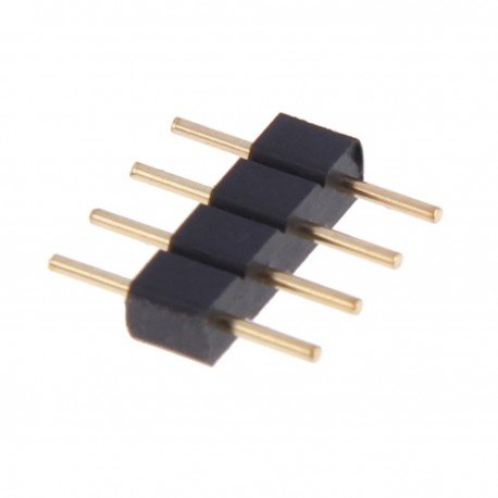
Male pins
Ky-022 infrared receiver module

Size: 6.4 * 7.4 * 5.1MM, acceptance angle 90o, working voltage 2.7-5.5V.
Frequency 37.9KHZ, receiving the distance 18 m.
Daylight rejection up to 500LUX, electromagnetic interference capability, built-in dedicated infrared IC.
Widely used: stereo, TV, VCR, CD, set-top boxes, digital photo frame, car audio, remote control toys, satellite receivers, hard drive, air conditioning, heating, fans, lighting and other appliances.
Pinout:
1 …. GND (-)
2 …. + 5V
3 …. Output (S)
Eight pushbuttons

A pcb

Download –> 8-channel infrared light control
source code
|
1 2 3 4 5 6 7 8 9 10 11 12 13 14 15 16 17 18 19 20 21 22 23 24 25 26 27 28 29 30 31 32 33 34 35 36 37 38 39 40 41 42 43 44 45 46 47 48 49 50 51 52 53 54 55 56 57 58 59 60 61 62 63 64 65 66 67 68 69 70 71 72 73 74 75 76 77 78 79 80 81 82 83 84 85 86 87 88 89 90 91 92 93 94 95 96 97 98 99 100 101 102 103 104 105 106 107 108 109 110 111 112 113 114 115 116 117 118 119 120 121 122 123 124 125 126 127 128 129 130 131 132 133 134 135 136 137 138 139 140 141 142 143 144 145 146 147 148 149 150 151 152 153 154 155 156 157 158 159 160 161 162 163 164 165 166 167 168 169 170 171 172 173 174 175 176 177 178 179 180 181 182 183 184 185 186 187 188 189 190 191 192 193 194 195 196 197 198 199 200 201 202 203 204 205 206 207 208 209 210 211 212 213 214 215 216 217 218 219 220 221 222 223 224 225 226 227 228 229 230 231 232 233 234 235 236 237 238 239 240 241 242 243 244 245 246 247 248 249 250 251 252 253 254 255 256 257 258 259 260 261 262 263 264 265 266 267 268 269 270 271 272 273 274 275 276 277 278 279 280 281 282 283 284 285 286 287 288 289 290 291 292 293 294 295 296 297 298 299 300 301 302 303 304 305 306 307 308 309 310 311 312 313 314 315 316 317 318 319 320 321 322 323 324 325 326 327 328 |
//Más proyectos en www.rogerbit.com #include <IRremote.h> #define RECV_PIN 2 //indicamos el pin por el que recibimos los datos del //sensor TSOP1838 IRrecv irrecv(RECV_PIN); decode_results results; int estadoBoton11 = 0; int estadoBoton12 = 0; int estadoBotonA5 = 0; int estadoBotonA0 = 0; int estadoBotonA1 = 0; int estadoBotonA2 = 0; int estadoBotonA3 = 0; int estadoBotonA4 = 0; int estado11 = 0; int estado12 = 0; int estadoA5 = 0; int estadoA0 = 0; int estadoA1 = 0; int estadoA2 = 0; int estadoA3 = 0; int estadoA4 = 0; //Pulsadores int botonPin11 =11; int botonPin12 =12; int botonPinA5 =A5; int botonPinA0 =A0; int botonPinA1 =A1; int botonPinA2 =A2; int botonPinA3 =A3; int botonPinA4 =A4; void setup() { Serial.begin(9600);//Velocidad del puerto //Definimos estos pines como salidas pinMode(3,OUTPUT); pinMode(4,OUTPUT); pinMode(5,OUTPUT); pinMode(6,OUTPUT); pinMode(7,OUTPUT); pinMode(8,OUTPUT); pinMode(9,OUTPUT); pinMode(10,OUTPUT); //Ponemos en estado Alto todas las salidas digitalWrite(3,HIGH); digitalWrite(4,HIGH); digitalWrite(5,HIGH); digitalWrite(6,HIGH); digitalWrite(7,HIGH); digitalWrite(8,HIGH); digitalWrite(9,HIGH); digitalWrite(10,HIGH); //Definimos estos pines como entrdas para los pulsadores pinMode(botonPin11, INPUT_PULLUP); pinMode(botonPin12, INPUT_PULLUP); pinMode(botonPinA5, INPUT_PULLUP); pinMode(botonPinA0, INPUT_PULLUP); pinMode(botonPinA1, INPUT_PULLUP); pinMode(botonPinA2, INPUT_PULLUP); pinMode(botonPinA3, INPUT_PULLUP); pinMode(botonPinA4, INPUT_PULLUP); irrecv.enableIRIn(); // Iniciamos la recepcion } void loop() { //Si tenemos datos de lectura debido a que se pulsa una tecla en el mando if (irrecv.decode(&results)) { //Mostramos por puerto serie dicho codigo en Hexadecimal(para depuracion) Serial.print("Codigo: 0x") ; Serial.println(results.value,HEX) ; //Pin 3 arduino IN1 en módulo relay de 8 canales if(results.value==0x2B||results.value==0x82B)//Apagado { digitalWrite(3,HIGH); estado11 = 0; } if(results.value==0x2A||results.value==0x82A)//Encendido { digitalWrite(3, LOW); estado11 = 1; } //Pin 4 arduino IN2 en módulo relay de 8 canales if(results.value==0x23||results.value==0x823)//Apagado { digitalWrite(4,HIGH); estado12 = 0; } if(results.value==0x27||results.value==0x827)//Encendido { digitalWrite(4, LOW); estado12 = 1; } //Pin 5 arduino IN3 en módulo relay de 8 canales if(results.value==0xB||results.value==0x80B)//Apagado { digitalWrite(5,HIGH); estadoA5 = 0; } if(results.value==0x3D||results.value==0x83D)//Encendido { digitalWrite(5,LOW); estadoA5 = 1; } //Pin 6 arduino IN4 en módulo relay de 8 canales if(results.value==0x30||results.value==0x830)//Apagado { digitalWrite(6,HIGH); estadoA0 = 0; } if(results.value==0x2F||results.value==0x82F)//Encendido { digitalWrite(6,LOW); estadoA0 = 1; } //Pin 7 arduino IN5 en módulo relay de 8 canales if(results.value==0x33||results.value==0x833)//Apagado { digitalWrite(7,HIGH); estadoA1 = 0; } if(results.value==0x31||results.value==0x831)//Encendido { digitalWrite(7,LOW); estadoA1 = 1; } //Pin 8 arduino IN6 en módulo relay de 8 canales if(results.value==0x21||results.value==0x821)//Apagado { digitalWrite(8,HIGH); estadoA2 = 0; } if(results.value==0x20||results.value==0x820)//Encendido { digitalWrite(8,LOW); estadoA2 = 1; } //Pin 9 arduino IN7 en módulo relay de 8 canales if(results.value==0x24||results.value==0x824)//Apagado { digitalWrite(9,HIGH); estadoA3 = 0; } if(results.value==0xE||results.value==0x80E)//Encendido { digitalWrite(9,LOW); estadoA3 = 1; } //Pin 10 arduino IN8 en módulo relay de 8 canales if(results.value==0x11||results.value==0x811)//Apagado { digitalWrite(10,HIGH); estadoA4 = 0; } if(results.value==0x10||results.value==0x810)//Encendido { digitalWrite(10,LOW); estadoA4 = 1; } irrecv.resume(); // Recibimos el siguiente valor del sensor } delay(100);//Retardo antirrebote para los pulsadores estadoBoton11 = digitalRead(botonPin11);//Leemos el pulsador para ver su estado estadoBoton12 = digitalRead(botonPin12);//Leemos el pulsador para ver su estado estadoBotonA5 = digitalRead(botonPinA5);//Leemos el pulsador para ver su estado estadoBotonA0 = digitalRead(botonPinA0);//Leemos el pulsador para ver su estado estadoBotonA1 = digitalRead(botonPinA1);//Leemos el pulsador para ver su estado estadoBotonA2 = digitalRead(botonPinA2);//Leemos el pulsador para ver su estado estadoBotonA3 = digitalRead(botonPinA3);//Leemos el pulsador para ver su estado estadoBotonA4 = digitalRead(botonPinA4);//Leemos el pulsador para ver su estado //Llama a una función if (estadoBoton11 == LOW) {//Si el pulsador está precionado se cumple esta condición luz11(); } //Llama a una función if (estadoBoton12 == LOW) {//Si el pulsador está precionado se cumple esta condición luz12(); } //Llama a una función if (estadoBotonA5 == LOW) {//Si el pulsador está precionado se cumple esta condición luzA5(); } //Llama a una función if (estadoBotonA0 == LOW) {//Si el pulsador está precionado se cumple esta condición luzA0(); } //Llama a una función if (estadoBotonA1 == LOW) {//Si el pulsador está precionado se cumple esta condición luzA1(); } //Llama a una función if (estadoBotonA2 == LOW) {//Si el pulsador está precionado se cumple esta condición luzA2(); } //Llama a una función if (estadoBotonA3 == LOW) {//Si el pulsador está precionado se cumple esta condición luzA3(); } //Llama a una función if (estadoBotonA4 == LOW) {//Si el pulsador está precionado se cumple esta condición luzA4(); } } //Función para encender la luz con el botón void luz11(){ if(estado11 ==0){//Si la variable estado es igual a 0 se cumple esta condición digitalWrite(3, LOW);// Encendemos el relay estado11 = 1;//Asignamos el valor 1 a la variable "estado" } else{ digitalWrite(3, HIGH);//Apagamos el relay estado11 = 0; } while(estadoBoton11 == LOW){ estadoBoton11 = digitalRead(11);//Se cumple esta condición mientras esté precionado el botón } } //Función para encender la luz con el botón void luz12(){ if(estado12 ==0){//Si la variable estado es igual a 0 se cumple esta condición digitalWrite(4, LOW);// Encendemos el relay estado12 = 1;//Asignamos el valor 1 a la variable "estado" } else{ digitalWrite(4, HIGH);//Apagamos el relay estado12 = 0; } while(estadoBoton12 == LOW){ estadoBoton12 = digitalRead(12);//Se cumple esta condición mientras esté precionado el botón } } //Función para encender la luz con el botón void luzA5(){ if(estadoA5 ==0){//Si la variable estado es igual a 0 se cumple esta condición digitalWrite(5, LOW);// Encendemos el relay estadoA5 = 1;//Asignamos el valor 1 a la variable "estado" } else{ digitalWrite(5, HIGH);//Apagamos el relay estadoA5 = 0; } while(estadoBotonA5 == LOW){ estadoBotonA5 = digitalRead(A5);//Se cumple esta condición mientras esté precionado el botón } } void luzA0(){ if(estadoA0 ==0){//Si la variable estado es igual a 0 se cumple esta condición digitalWrite(6, LOW);// Encendemos el relay estadoA0 = 1;//Asignamos el valor 1 a la variable "estado" } else{ digitalWrite(6, HIGH);//Apagamos el relay estadoA0 = 0; } while(estadoBotonA0 == LOW){ estadoBotonA0 = digitalRead(A0);//Se cumple esta condición mientras esté precionado el botón } } //Función para encender la luz con el botón void luzA1(){ if(estadoA1 ==0){//Si la variable estado es igual a 0 se cumple esta condición digitalWrite(7, LOW);// Encendemos el relay estadoA1 = 1;//Asignamos el valor 1 a la variable "estado" } else{ digitalWrite(7, HIGH);//Apagamos el relay estadoA1 = 0; } while(estadoBotonA1 == LOW){ estadoBotonA1 = digitalRead(A1);//Se cumple esta condición mientras esté precionado el botón } } //Función para encender la luz con el botón void luzA2(){ if(estadoA2 ==0){//Si la variable estado es igual a 0 se cumple esta condición digitalWrite(8, LOW);// Encendemos el relay estadoA2 = 1;//Asignamos el valor 1 a la variable "estado" } else{ digitalWrite(8, HIGH);//Apagamos el relay estadoA2 = 0; } while(estadoBotonA2 == LOW){ estadoBotonA2 = digitalRead(A2);//Se cumple esta condición mientras esté precionado el botón } } //Función para encender la luz con el botón void luzA3(){ if(estadoA3 ==0){//Si la variable estado es igual a 0 se cumple esta condición digitalWrite(9, LOW);// Encendemos el relay estadoA3 = 1;//Asignamos el valor 1 a la variable "estado" } else{ digitalWrite(9, HIGH);//Apagamos el relay estadoA3 = 0; } while(estadoBotonA3 == LOW){ estadoBotonA3 = digitalRead(A3);//Se cumple esta condición mientras esté precionado el botón } } //Función para encender la luz con el botón void luzA4(){ if(estadoA4 ==0){//Si la variable estado es igual a 0 se cumple esta condición digitalWrite(10, LOW);// Encendemos el relay estadoA4 = 1;//Asignamos el valor 1 a la variable "estado" } else{ digitalWrite(10, HIGH);//Apagamos el relay estadoA4 = 0; } while(estadoBotonA4 == LOW){ estadoBotonA4 = digitalRead(A4);//Se cumple esta condición mientras esté precionado el botón } } |
RECOMMENDED PROJECT