
In this tutorial we will see how to do a synchronized radio frequency control, since one control can control the other. With APC220 modules, which according to the manufacturer can reach a distance of up to one kilometer, under appropriate conditions, are transparent radio modules, since everything that it sends through the serial port, is what will be transmitted. As the brains of the project we will use a couple of arduinos mini pro.
You may be interested in projects in Arduino, pic, robotics, telecommunications, subscribe http://www.youtube.com/user/carlosvolt?sub_confirmation=1 videos with full source code and diagrams

Plates and modules used in this project
Arduino mini pro
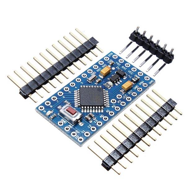
The Arduino Pro Mini is a microcontroller board based on the ATmega328.
It has 14 digital input/output pins (of which 6 can be used as PWM outputs), 6 analog inputs, an integrated resonator, a reset button and holes to mount pin headers. A six-pin header can be connected to an FTDI cable or Sparkfun connection board to provide USB power and communication to the board.
The Arduino Pro Mini is designed for semi-permanent installation in objects or exhibitions. The board comes without pre-assembled headers, allowing the use of various types of connectors or direct cable welding. The pin design is compatible with the Arduino Mini.
There are two versions of the Pro Mini. One runs at 3.3V and 8 MHz, the other at 5V and 16 MHz.
| microcontroller | ATmega328 * |
| Board power supply | 3.35-12 V (3.3 V model) or 5-12 V (5 V model) |
| Circuit operating voltage | 3.3V or 5V (depending on model) |
| Digital I/O Pins | 14 |
| PWM pins | 6 6 |
| Uart | 1 |
| Spi | 1 |
| I2C | 1 |
| Analog input pins | 6 6 |
| External outages | 2 |
| DC current per I/O pin | 40 mA |
| Flash memory | 32 KB of which 2 KB used by the bootloader * |
| Sram | 2 KB * |
| Eeprom | 1 KB * |
| Clock speed | 8 MHz (3.3V versions) or 16 MHz (5V versions) |
Module Apc220
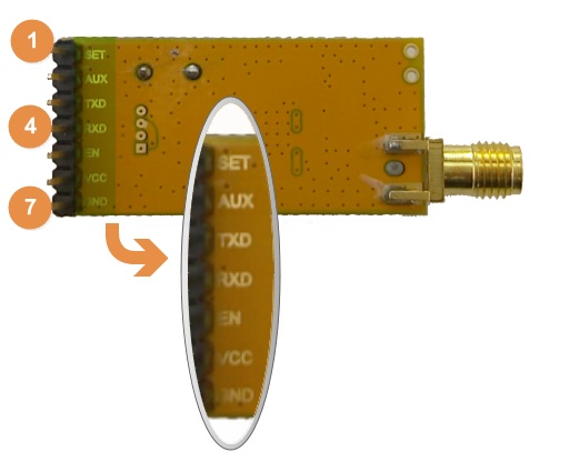
The APC220 radio data module is a high-power and highly versatile radio solution, it is easy to set up and integrate into any project that requires a wireless RF link. It is perfect for robotic applications if you need wireless control. You can connect one of these modules to your MCU via the TTL interface, and connect to your PC with another APC220 module via a TTL/USB converter.
specification
- Working frequency: 420 MHz to 450 MHz
- Power: 3.5-5.5V
- Current: <25-35mA
- Working temperature: -20oC + 70oC
- Range: 1200 m (1200 bps)
- Interface: UART/ TTL
- Transmission speed: 1200-19200 bps
- Transmission speed (air): 1200-19200 bps
- Receive buffer: 256 bytes
- Size: 37mm × 17mm × 6.6mm
- Weight: 30g
PinOut
| pin | Definition | detail |
|---|---|---|
| 1 | Set | Set parameters (low) |
| 2 | Aux | UART signal- Transmission (low) Transmission (high) |
| 3 | TXD | UART TX |
| 4 | RXD | UART RX |
| 5 | is | Turn off the device when <0.5 V. Enable the device when you leave it offline or apply> 1.6 V |
| 6 | Vdc | 3.3V-5.5V power |
| 7 | Gnd | Earth 0V |
Download RF-Magic
Datasheet
Run APC22X_V12A.exe (RF-Magic) as an administrator if your system is not Windows XP.

NOTE: In the software you will recognize the APC220 module and COMX serial port automatically once we open it. Check in Device Manager to verify the correct COM port.
Configure RF-magic as in the red square frame below (default setting), and click Write W to enter your settings, then click Read R to read the parameters you have set.

configuration

Writing and reading settings
| parameter | rank | default |
|---|---|---|
| RF frequency | 1KHz resolution, 100Hz ± accuracy | 434MHz |
| TRx RF Rate | 1200, 2400, 4800, 9600, 19200 bps | 9600bps |
| RF power | 0-9 | 9 |
| Serial rate | 1200, 2400, 4800, 9600, 19200, 38400, 57600bps | 9600bps |
| NET ID | 0-65535 (16-bit) | 12345 |
| NODE ID | 123456789012 | |
| Patity Series | Disable, the strange Patity, even Patity | disable |
Configure the other APC220 module in the same way, with the same parameter settings.
8-channel Relay rele module

- Operating Voltage: 5V DC
- Control Signal: TTL (3.3V or 5V)
- Relays No.: 8 CH
- Max capacity: 10A/250VAC, 10A/30VDC
- Max current: 10A (NO), 5A (NC)
- Action time: 10 ms/5 ms
- To activate output NO: 0 Volts
2 Jumper

16 3mm Led

16 1KOhm Led
Female pins

16 Pushbuttons
Male pins

2 sockets for Arduino mini pro
Pcb

Download the gerber file free from here –> https://www.pcbway.com/project/shareproject/Dual_Synchronized_Radio_Frequency_Control_for_Motor_Lights_and_more.html
Source Code (for reverse logic relay module)
|
1 2 3 4 5 6 7 8 9 10 11 12 13 14 15 16 17 18 19 20 21 22 23 24 25 26 27 28 29 30 31 32 33 34 35 36 37 38 39 40 41 42 43 44 45 46 47 48 49 50 51 52 53 54 55 56 57 58 59 60 61 62 63 64 65 66 67 68 69 70 71 72 73 74 75 76 77 78 79 80 81 82 83 84 85 86 87 88 89 90 91 92 93 94 95 96 97 98 99 100 101 102 103 104 105 106 107 108 109 110 111 112 113 114 115 116 117 118 119 120 121 122 123 124 125 126 127 128 129 130 131 132 133 134 135 136 137 138 139 140 141 142 143 144 145 146 147 148 149 150 151 152 153 154 155 156 157 158 159 160 161 162 163 164 165 166 167 168 169 170 171 172 173 174 175 176 177 178 179 180 181 182 183 184 185 186 187 188 189 190 191 192 193 194 195 196 197 198 199 200 201 202 203 204 205 206 207 208 209 210 211 212 213 214 215 216 217 218 219 220 221 222 223 224 225 226 227 228 229 230 231 232 233 234 235 236 237 238 239 240 241 242 243 244 245 246 247 248 249 250 251 252 253 254 255 256 257 258 259 260 261 262 263 264 265 266 267 268 269 270 271 272 273 274 275 276 277 278 279 280 281 282 283 284 285 286 287 288 289 290 291 292 293 294 295 296 297 298 299 300 301 302 303 304 305 306 307 308 309 310 311 312 313 |
//Variables String cadena; int pul2 = 0; int pul3 = 0; int pul4 = 0; int pul5 = 0; int pul6 = 0; int pul7 = 0; int pul8 = 0; int pul9 = 0; int estado2 = 0; int estado3 = 0; int estado4 = 0; int estado5 = 0; int estado6 = 0; int estado7 = 0; int estado8 = 0; int estado9 = 0; int estCadena2=0; int estCadena3=0; int estCadena4=0; int estCadena5=0; int estCadena6=0; int estCadena7=0; int estCadena8=0; int estCadena9=0; //Pines para las luces int luz10 = 10; int luz11 = 11; int luz12 = 12; int luz13 = 13; int luzA0 = A0; int luzA1 = A1; int luzA2 = A2; int luzA3 = A3; void setup () { Serial.begin(9600);// setea la velocidad del puerto serial debe conincidir con la del módulo apc220 //Seteamos los pines de los pulsadores como entradas y activamos resistores de pullup pinMode(2, INPUT_PULLUP); pinMode(3, INPUT_PULLUP); pinMode(4, INPUT_PULLUP); pinMode(5, INPUT_PULLUP); pinMode(6, INPUT_PULLUP); pinMode(7, INPUT_PULLUP); pinMode(8, INPUT_PULLUP); pinMode(9, INPUT_PULLUP); //Seteamos los pines como salidas para encender led o activar relay pinMode(luz10, OUTPUT); pinMode(luz11, OUTPUT); pinMode(luz12, OUTPUT); pinMode(luz13, OUTPUT); pinMode(luzA0, OUTPUT); pinMode(luzA1, OUTPUT); pinMode(luzA2, OUTPUT); pinMode(luzA3, OUTPUT); //Activamos estas lineas si usamos módulos relay con lógica invertida (activa en con LOW y desactiva con HIGH) digitalWrite(10, HIGH); digitalWrite(11, HIGH); digitalWrite(12, HIGH); digitalWrite(13, HIGH); digitalWrite(A0, HIGH); digitalWrite(A1, HIGH); digitalWrite(A2, HIGH); digitalWrite(A3, HIGH); delay(10); } void loop () { //leemos los caractres que ingresan al puerto serie y obtenemos una cadena if (Serial.available()) { cadena = String(""); while (Serial.available()) { cadena = cadena + char(Serial.read()); delay(1); } } //Lectura de botones, si hemos apretados un pulsador asignamos un LOW a la variable pul2 = digitalRead(2); pul3 = digitalRead(3); pul4 = digitalRead(4); pul5 = digitalRead(5); pul6 = digitalRead(6); pul7 = digitalRead(7); pul8 = digitalRead(8); pul9 = digitalRead(9); //********************* //Enciende o apaga la luz if (pul2 == LOW) {//Si el pulsador 2 está precionado se cumple esta condición pul2 = digitalRead(2);//Leemos el estado del botón nuevamente if(estado2 ==0){//Si la variable estado2 es igual a 0 se cumple esta condición Serial.print("luz2on");// Enviamos esta cadena de caracteres x el puerto serial para encender la luz estado2 =1;//Asignamos el valor 1 a la variable "estado2" } else{ Serial.print("luz2off");//Enviamos esta cadena para apagar la luz estado2 =0; } while(pul2 == LOW){ pul2 = digitalRead(2);//Se cumple esta condición mientras esté precionado el botón } } //----------------------------------------------------------------------------------- //Enciende o apaga la luz if (pul3 == LOW) {//Si el pulsador 3 está precionado se cumple esta condición pul3 = digitalRead(3);//Leemos el estado del botón nuevamente if(estado3 ==0){//Si la variable estado3 es igual a 0 se cumple esta condición Serial.print("luz3on");// Enviamos esta cadena de caracteres x el puerto serial para encender la luz estado3 =1;//Asignamos el valor 1 a la variable "estado3" } else{ Serial.print("luz3off");//Enviamos esta cadena para apagar la luz estado3 =0; } while(pul3 == LOW){ pul3 = digitalRead(3);//Se cumple esta condición mientras esté precionado el botón } } //----------------------------------------------------------------------------------- //Enciende o apaga la luz if (pul4 == LOW) {//Si el pulsador 4 está precionado se cumple esta condición pul4 = digitalRead(4);//Leemos el estado del botón nuevamente if(estado4 ==0){//Si la variable estado4 es igual a 0 se cumple esta condición Serial.print("luz4on");// Enviamos esta cadena de caracteres x el puerto serial para encender la luz estado4 =1;//Asignamos el valor 1 a la variable "estado4" } else{ Serial.print("luz4off");//Enviamos esta cadena para apagar la luz estado4 =0; } while(pul4 == LOW){ pul4 = digitalRead(4);//Se cumple esta condición mientras esté precionado el botón } } //----------------------------------------------------------------------------------- //Enciende o apaga la luz if (pul5 == LOW) {//Si el pulsador 5 está precionado se cumple esta condición pul5 = digitalRead(5);//Leemos el estado del botón nuevamente if(estado5 ==0){//Si la variable estado5 es igual a 0 se cumple esta condición Serial.print("luz5on");// Enviamos esta cadena de caracteres x el puerto serial para encender la luz estado5 =1;//Asignamos el valor 1 a la variable "estado5" } else{ Serial.print("luz5off");//Enviamos esta cadena para apagar la luz estado5 =0; } while(pul5 == LOW){ pul5 = digitalRead(5);//Se cumple esta condición mientras esté precionado el botón } } //----------------------------------------------------------------------------------- //Enciende o apaga la luz if (pul6 == LOW) {//Si el pulsador 6 está precionado se cumple esta condición pul6 = digitalRead(6);//Leemos el estado del botón nuevamente if(estado6 ==0){//Si la variable estado6 es igual a 0 se cumple esta condición Serial.print("luz6on");// Enviamos esta cadena de caracteres x el puerto serial para encender la luz estado6 =1;//Asignamos el valor 1 a la variable "estado6" } else{ Serial.print("luz6off");//Enviamos esta cadena para apagar la luz estado6 =0; } while(pul6 == LOW){ pul6 = digitalRead(6);//Se cumple esta condición mientras esté precionado el botón } } //----------------------------------------------------------------------------------- //Enciende o apaga la luz if (pul7 == LOW) {//Si el pulsador 7 está precionado se cumple esta condición pul7 = digitalRead(7);//Leemos el estado del botón nuevamente if(estado7 ==0){//Si la variable estado7 es igual a 0 se cumple esta condición Serial.print("luz7on");// Enviamos esta cadena de caracteres x el puerto serial para encender la luz estado7 =1;//Asignamos el valor 1 a la variable "estado7" } else{ Serial.print("luz7off");//Enviamos esta cadena para apagar la luz estado7 =0; } while(pul7 == LOW){ pul7 = digitalRead(7);//Se cumple esta condición mientras esté precionado el botón } } //----------------------------------------------------------------------------------- //Enciende o apaga la luz if (pul8 == LOW) {//Si el pulsador 8 está precionado se cumple esta condición pul8 = digitalRead(8);//Leemos el estado del botón nuevamente if(estado8 ==0){//Si la variable estado8 es igual a 0 se cumple esta condición Serial.print("luz8on");// Enviamos esta cadena de caracteres x el puerto serial para encender la luz estado8 =1;//Asignamos el valor 1 a la variable "estado8" } else{ Serial.print("luz8off");//Enviamos esta cadena para apagar la luz estado8 =0; } while(pul8 == LOW){ pul8 = digitalRead(8);//Se cumple esta condición mientras esté precionado el botón } } //----------------------------------------------------------------------------------- //Enciende o apaga la luz if (pul9 == LOW) {//Si el pulsador 9 está precionado se cumple esta condición pul9 = digitalRead(9);//Leemos el estado del botón nuevamente if(estado9 ==0){//Si la variable estado9 es igual a 0 se cumple esta condición Serial.print("luz9on");// Enviamos esta cadena de caracteres x el puerto serial para encender la luz estado9 =1;//Asignamos el valor 1 a la variable "estado9" } else{ Serial.print("luz9off");//Enviamos esta cadena para apagar la luz estado9 =0; } while(pul9 == LOW){ pul9 = digitalRead(9);//Se cumple esta condición mientras esté precionado el botón } } //----------------------------------------------------------------------------------- delay(50); //************** //-------------------------------------------------------------------- if (cadena == "luz2on" && estCadena2 == 0) {//Compara el valor de la cadena obetinada y estCadena2 vale 0 digitalWrite (luz10,LOW);//Encendemos el relay (si que es de lógica invertida), pero el led se apaga Serial.print("luz2on");//Envía esta cadena estCadena2 = 1; estado2 =1; } if (cadena == "luz2off" && estCadena2 == 1) {//compara el valor de la cadena obetinada y estCadena2 vale 1 digitalWrite (luz10,HIGH);//Apagamos el relay (si que es de lógica invertida), pero el led se enciende Serial.print("luz2off");//Envía esta cadena estCadena2 = 0; estado2 =0; } //-------------------------------------------------------------------- if (cadena == "luz3on" && estCadena3 == 0) { digitalWrite (luz11,LOW); Serial.print("luz3on"); estCadena3 = 1; estado3 =1; } if (cadena == "luz3off" && estCadena3 == 1) { digitalWrite (luz11,HIGH); Serial.print("luz3off"); estCadena3 = 0; estado3 =0; } //-------------------------------------------------------------------- if (cadena == "luz4on" && estCadena4 == 0) { digitalWrite (luz12,LOW); Serial.print("luz4on"); estCadena4 = 1; estado4 =1; } if (cadena == "luz4off" && estCadena4 == 1) { digitalWrite (luz12,HIGH); Serial.print("luz4off"); estCadena4 = 0; estado4 =0; } //-------------------------------------------------------------------- if (cadena == "luz5on" && estCadena5 == 0) { digitalWrite (luz13,LOW); Serial.print("luz5on"); estCadena5 = 1; estado5 =1; } if (cadena == "luz5off" && estCadena5 == 1) { digitalWrite (luz13,HIGH); Serial.print("luz5off"); estCadena5 = 0; estado5 =0; } //-------------------------------------------------------------------- if (cadena == "luz6on" && estCadena6 == 0) { digitalWrite (luzA0,LOW); Serial.print("luz6on"); estCadena6 = 1; estado6 =1; } if (cadena == "luz6off" && estCadena6 == 1) { digitalWrite (luzA0,HIGH); Serial.print("luz6off"); estCadena6 = 0; estado6 =0; } //-------------------------------------------------------------------- if (cadena == "luz7on" && estCadena7 == 0) { digitalWrite (luzA1,LOW); Serial.print("luz7on"); estCadena7 = 1; estado7 =1; } if (cadena == "luz7off" && estCadena7 == 1) { digitalWrite (luzA1,HIGH); Serial.print("luz7off"); estCadena7 = 0; estado7 =0; } //-------------------------------------------------------------------- if (cadena == "luz8on" && estCadena8 == 0) { digitalWrite (luzA2,LOW); Serial.print("luz8on"); estCadena8 = 1; estado8 =1; } if (cadena == "luz8off" && estCadena8 == 1) { digitalWrite (luzA2,HIGH); Serial.print("luz8off"); estCadena8 = 0; estado8 =0; } //-------------------------------------------------------------------- if (cadena == "luz9on" && estCadena9 == 0) { digitalWrite (luzA3,LOW); Serial.print("luz9on"); estCadena9 = 1; estado9 =1; } if (cadena == "luz9off" && estCadena9 == 1) { digitalWrite (luzA3,HIGH); Serial.print("luz9off"); estCadena9 = 0; estado9 =0; } } |
Source Code (Relay module without reverse logic)
|
1 2 3 4 5 6 7 8 9 10 11 12 13 14 15 16 17 18 19 20 21 22 23 24 25 26 27 28 29 30 31 32 33 34 35 36 37 38 39 40 41 42 43 44 45 46 47 48 49 50 51 52 53 54 55 56 57 58 59 60 61 62 63 64 65 66 67 68 69 70 71 72 73 74 75 76 77 78 79 80 81 82 83 84 85 86 87 88 89 90 91 92 93 94 95 96 97 98 99 100 101 102 103 104 105 106 107 108 109 110 111 112 113 114 115 116 117 118 119 120 121 122 123 124 125 126 127 128 129 130 131 132 133 134 135 136 137 138 139 140 141 142 143 144 145 146 147 148 149 150 151 152 153 154 155 156 157 158 159 160 161 162 163 164 165 166 167 168 169 170 171 172 173 174 175 176 177 178 179 180 181 182 183 184 185 186 187 188 189 190 191 192 193 194 195 196 197 198 199 200 201 202 203 204 205 206 207 208 209 210 211 212 213 214 215 216 217 218 219 220 221 222 223 224 225 226 227 228 229 230 231 232 233 234 235 236 237 238 239 240 241 242 243 244 245 246 247 248 249 250 251 252 253 254 255 256 257 258 259 260 261 262 263 264 265 266 267 268 269 270 271 272 273 274 275 276 277 278 279 280 281 282 283 284 285 286 287 288 289 290 291 292 293 294 295 296 297 298 299 300 301 302 303 304 305 306 307 308 309 310 311 312 313 |
//Variables String cadena; int pul2 = 0; int pul3 = 0; int pul4 = 0; int pul5 = 0; int pul6 = 0; int pul7 = 0; int pul8 = 0; int pul9 = 0; int estado2 = 1; int estado3 = 1; int estado4 = 1; int estado5 = 1; int estado6 = 1; int estado7 = 1; int estado8 = 1; int estado9 = 1; int estCadena2=1; int estCadena3=1; int estCadena4=1; int estCadena5=1; int estCadena6=1; int estCadena7=1; int estCadena8=1; int estCadena9=1; //Pines para las luces int luz10 = 10; int luz11 = 11; int luz12 = 12; int luz13 = 13; int luzA0 = A0; int luzA1 = A1; int luzA2 = A2; int luzA3 = A3; void setup () { Serial.begin(9600);// setea la velocidad del puerto serial debe conincidir con la del módulo apc220 //Seteamos los pines de los pulsadores como entradas y activamos resistores de pullup pinMode(2, INPUT_PULLUP); pinMode(3, INPUT_PULLUP); pinMode(4, INPUT_PULLUP); pinMode(5, INPUT_PULLUP); pinMode(6, INPUT_PULLUP); pinMode(7, INPUT_PULLUP); pinMode(8, INPUT_PULLUP); pinMode(9, INPUT_PULLUP); //Seteamos los pines como salidas para encender led o activar relay pinMode(luz10, OUTPUT); pinMode(luz11, OUTPUT); pinMode(luz12, OUTPUT); pinMode(luz13, OUTPUT); pinMode(luzA0, OUTPUT); pinMode(luzA1, OUTPUT); pinMode(luzA2, OUTPUT); pinMode(luzA3, OUTPUT); //Activamos estas lineas si usamos módulos relay con lógica invertida (activa en con LOW y desactiva con HIGH) // digitalWrite(10, HIGH); // digitalWrite(11, HIGH); // digitalWrite(12, HIGH); // digitalWrite(13, HIGH); // digitalWrite(A0, HIGH); // digitalWrite(A1, HIGH); // digitalWrite(A2, HIGH); // digitalWrite(A3, HIGH); delay(10); } void loop () { //leemos los caractres que ingresan al puerto serie y obtenemos una cadena if (Serial.available()) { cadena = String(""); while (Serial.available()) { cadena = cadena + char(Serial.read()); delay(1); } } //Lectura de botones, si hemos apretados un pulsador asignamos un LOW a la variable pul2 = digitalRead(2); pul3 = digitalRead(3); pul4 = digitalRead(4); pul5 = digitalRead(5); pul6 = digitalRead(6); pul7 = digitalRead(7); pul8 = digitalRead(8); pul9 = digitalRead(9); //********************* //Enciende o apaga la luz if (pul2 == LOW) {//Si el pulsador 2 está precionado se cumple esta condición pul2 = digitalRead(2);//Leemos el estado del botón nuevamente if(estado2 ==0){//Si la variable estado2 es igual a 0 se cumple esta condición Serial.print("luz2on");// Enviamos esta cadena de caracteres x el puerto serial para encender la luz estado2 =1;//Asignamos el valor 1 a la variable "estado2" } else{ Serial.print("luz2off");//Enviamos esta cadena para apagar la luz estado2 =0; } while(pul2 == LOW){ pul2 = digitalRead(2);//Se cumple esta condición mientras esté precionado el botón } } //----------------------------------------------------------------------------------- //Enciende o apaga la luz if (pul3 == LOW) {//Si el pulsador 3 está precionado se cumple esta condición pul3 = digitalRead(3);//Leemos el estado del botón nuevamente if(estado3 ==0){//Si la variable estado3 es igual a 0 se cumple esta condición Serial.print("luz3on");// Enviamos esta cadena de caracteres x el puerto serial para encender la luz estado3 =1;//Asignamos el valor 1 a la variable "estado3" } else{ Serial.print("luz3off");//Enviamos esta cadena para apagar la luz estado3 =0; } while(pul3 == LOW){ pul3 = digitalRead(3);//Se cumple esta condición mientras esté precionado el botón } } //----------------------------------------------------------------------------------- //Enciende o apaga la luz if (pul4 == LOW) {//Si el pulsador 4 está precionado se cumple esta condición pul4 = digitalRead(4);//Leemos el estado del botón nuevamente if(estado4 ==0){//Si la variable estado4 es igual a 0 se cumple esta condición Serial.print("luz4on");// Enviamos esta cadena de caracteres x el puerto serial para encender la luz estado4 =1;//Asignamos el valor 1 a la variable "estado4" } else{ Serial.print("luz4off");//Enviamos esta cadena para apagar la luz estado4 =0; } while(pul4 == LOW){ pul4 = digitalRead(4);//Se cumple esta condición mientras esté precionado el botón } } //----------------------------------------------------------------------------------- //Enciende o apaga la luz if (pul5 == LOW) {//Si el pulsador 5 está precionado se cumple esta condición pul5 = digitalRead(5);//Leemos el estado del botón nuevamente if(estado5 ==0){//Si la variable estado5 es igual a 0 se cumple esta condición Serial.print("luz5on");// Enviamos esta cadena de caracteres x el puerto serial para encender la luz estado5 =1;//Asignamos el valor 1 a la variable "estado5" } else{ Serial.print("luz5off");//Enviamos esta cadena para apagar la luz estado5 =0; } while(pul5 == LOW){ pul5 = digitalRead(5);//Se cumple esta condición mientras esté precionado el botón } } //----------------------------------------------------------------------------------- //Enciende o apaga la luz if (pul6 == LOW) {//Si el pulsador 6 está precionado se cumple esta condición pul6 = digitalRead(6);//Leemos el estado del botón nuevamente if(estado6 ==0){//Si la variable estado6 es igual a 0 se cumple esta condición Serial.print("luz6on");// Enviamos esta cadena de caracteres x el puerto serial para encender la luz estado6 =1;//Asignamos el valor 1 a la variable "estado6" } else{ Serial.print("luz6off");//Enviamos esta cadena para apagar la luz estado6 =0; } while(pul6 == LOW){ pul6 = digitalRead(6);//Se cumple esta condición mientras esté precionado el botón } } //----------------------------------------------------------------------------------- //Enciende o apaga la luz if (pul7 == LOW) {//Si el pulsador 7 está precionado se cumple esta condición pul7 = digitalRead(7);//Leemos el estado del botón nuevamente if(estado7 ==0){//Si la variable estado7 es igual a 0 se cumple esta condición Serial.print("luz7on");// Enviamos esta cadena de caracteres x el puerto serial para encender la luz estado7 =1;//Asignamos el valor 1 a la variable "estado7" } else{ Serial.print("luz7off");//Enviamos esta cadena para apagar la luz estado7 =0; } while(pul7 == LOW){ pul7 = digitalRead(7);//Se cumple esta condición mientras esté precionado el botón } } //----------------------------------------------------------------------------------- //Enciende o apaga la luz if (pul8 == LOW) {//Si el pulsador 8 está precionado se cumple esta condición pul8 = digitalRead(8);//Leemos el estado del botón nuevamente if(estado8 ==0){//Si la variable estado8 es igual a 0 se cumple esta condición Serial.print("luz8on");// Enviamos esta cadena de caracteres x el puerto serial para encender la luz estado8 =1;//Asignamos el valor 1 a la variable "estado8" } else{ Serial.print("luz8off");//Enviamos esta cadena para apagar la luz estado8 =0; } while(pul8 == LOW){ pul8 = digitalRead(8);//Se cumple esta condición mientras esté precionado el botón } } //----------------------------------------------------------------------------------- //Enciende o apaga la luz if (pul9 == LOW) {//Si el pulsador 9 está precionado se cumple esta condición pul9 = digitalRead(9);//Leemos el estado del botón nuevamente if(estado9 ==0){//Si la variable estado9 es igual a 0 se cumple esta condición Serial.print("luz9on");// Enviamos esta cadena de caracteres x el puerto serial para encender la luz estado9 =1;//Asignamos el valor 1 a la variable "estado9" } else{ Serial.print("luz9off");//Enviamos esta cadena para apagar la luz estado9 =0; } while(pul9 == LOW){ pul9 = digitalRead(9);//Se cumple esta condición mientras esté precionado el botón } } //----------------------------------------------------------------------------------- delay(50); //************** //-------------------------------------------------------------------- if (cadena == "luz2on" && estCadena2 == 0) {//Compara el valor de la cadena obetinada y estCadena2 vale 0 digitalWrite (luz10,LOW);//Encendemos el relay (si que es de lógica invertida), pero el led se apaga Serial.print("luz2on");//Envía esta cadena estCadena2 = 1; estado2 =1; } if (cadena == "luz2off" && estCadena2 == 1) {//compara el valor de la cadena obetinada y estCadena2 vale 1 digitalWrite (luz10,HIGH);//Apagamos el relay (si que es de lógica invertida), pero el led se enciende Serial.print("luz2off");//Envía esta cadena estCadena2 = 0; estado2 =0; } //-------------------------------------------------------------------- if (cadena == "luz3on" && estCadena3 == 0) { digitalWrite (luz11,LOW); Serial.print("luz3on"); estCadena3 = 1; estado3 =1; } if (cadena == "luz3off" && estCadena3 == 1) { digitalWrite (luz11,HIGH); Serial.print("luz3off"); estCadena3 = 0; estado3 =0; } //-------------------------------------------------------------------- if (cadena == "luz4on" && estCadena4 == 0) { digitalWrite (luz12,LOW); Serial.print("luz4on"); estCadena4 = 1; estado4 =1; } if (cadena == "luz4off" && estCadena4 == 1) { digitalWrite (luz12,HIGH); Serial.print("luz4off"); estCadena4 = 0; estado4 =0; } //-------------------------------------------------------------------- if (cadena == "luz5on" && estCadena5 == 0) { digitalWrite (luz13,LOW); Serial.print("luz5on"); estCadena5 = 1; estado5 =1; } if (cadena == "luz5off" && estCadena5 == 1) { digitalWrite (luz13,HIGH); Serial.print("luz5off"); estCadena5 = 0; estado5 =0; } //-------------------------------------------------------------------- if (cadena == "luz6on" && estCadena6 == 0) { digitalWrite (luzA0,LOW); Serial.print("luz6on"); estCadena6 = 1; estado6 =1; } if (cadena == "luz6off" && estCadena6 == 1) { digitalWrite (luzA0,HIGH); Serial.print("luz6off"); estCadena6 = 0; estado6 =0; } //-------------------------------------------------------------------- if (cadena == "luz7on" && estCadena7 == 0) { digitalWrite (luzA1,LOW); Serial.print("luz7on"); estCadena7 = 1; estado7 =1; } if (cadena == "luz7off" && estCadena7 == 1) { digitalWrite (luzA1,HIGH); Serial.print("luz7off"); estCadena7 = 0; estado7 =0; } //-------------------------------------------------------------------- if (cadena == "luz8on" && estCadena8 == 0) { digitalWrite (luzA2,LOW); Serial.print("luz8on"); estCadena8 = 1; estado8 =1; } if (cadena == "luz8off" && estCadena8 == 1) { digitalWrite (luzA2,HIGH); Serial.print("luz8off"); estCadena8 = 0; estado8 =0; } //-------------------------------------------------------------------- if (cadena == "luz9on" && estCadena9 == 0) { digitalWrite (luzA3,LOW); Serial.print("luz9on"); estCadena9 = 1; estado9 =1; } if (cadena == "luz9off" && estCadena9 == 1) { digitalWrite (luzA3,HIGH); Serial.print("luz9off"); estCadena9 = 0; estado9 =0; } } |
RECOMMENDED VIDEOS